Retro-1970s styling and power in a compact chassis.
Next up: The preamp. A common feature of vintage equipment is a strong range of tone control, and some amount would be beneficial to the target speaker system either way. That meant using ESP's Project 97. The board was ordered from ESP, received, populated with NE5532 opamps and 1% metal film resistors, and then powered up on the bench. An immediate, faint trio of pfft sounds informed me that I was up way too late at night, and had reversed the power supply leads to the board. Oops.
With the three blown opamps replaced and the wiring correctly attached, the board tested successfully, and I finally wired it into the audio path and regulated power supply:
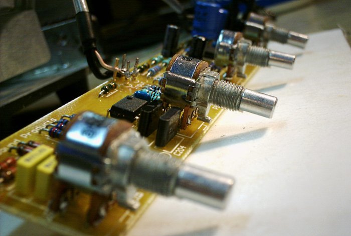
Figure 14. The preamp board, fully connected.
The white object is a sheet of Teflon plastic. I tend to get lots of solder scrap and other conductive things on my bench while working, so a layer of clean insulating material is always a good idea when connecting power to a loose board. The Teflon plastic is ideal for navigating around debris because, true to form, nothing sticks to it.
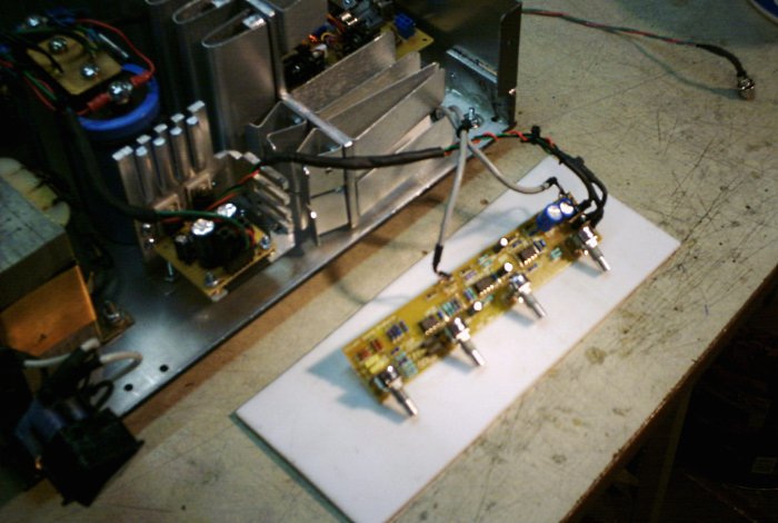
Figure 15. Another view of the connected preamp.
The last step was to prepare the front panel and mount the preamp accordingly. Per the previous round of measurements and fabrication, it fit neatly over the slot at the front of the main heatsink.
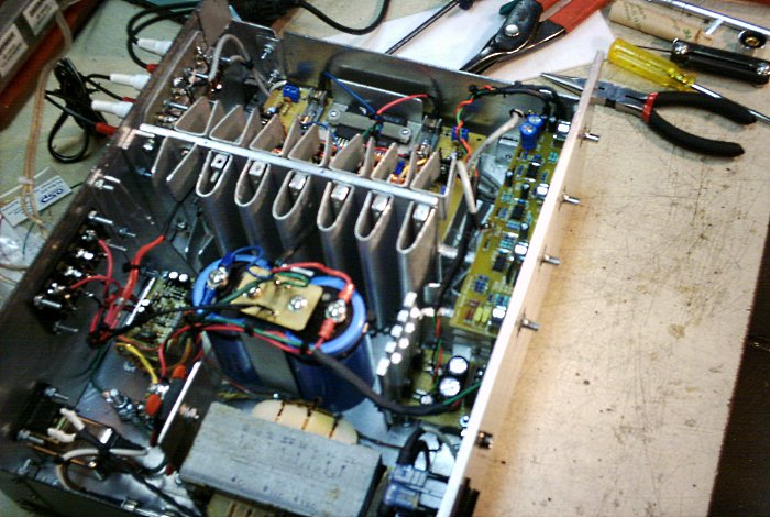
Figure 16. The preamp, installed on the front panel.
The last step before completing the finishing work was to install the output muting relay.
Power amplifiers do have a couple undesirable traits. The worst is a failure that puts DC voltage on the output, in which case the speaker must be protected rapidly or it will also fail. Second, a normal power-on can produce a sharp "pop" and a normal shutdown can generate whines, grunts, squeales, and other awkward noises as the supply voltage collapses. ESP Project 33 is designed to deal with these situations. In keeping with the 1970s theme, I modified a couple component values to produce a 4-second turn-on delay, but it is otherwise stock. To simplify the mounting in the chassis, the P33 board and relay were combined into a single assembly.
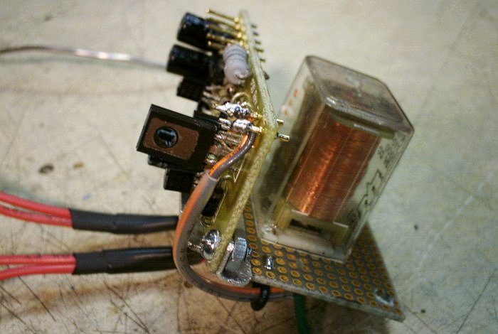
Figure 17. The muting relay assembly.
The assembly was bench tested, then mounted in the chassis under the speaker bracket. The installed assembly is also visible in Figure 16, above.
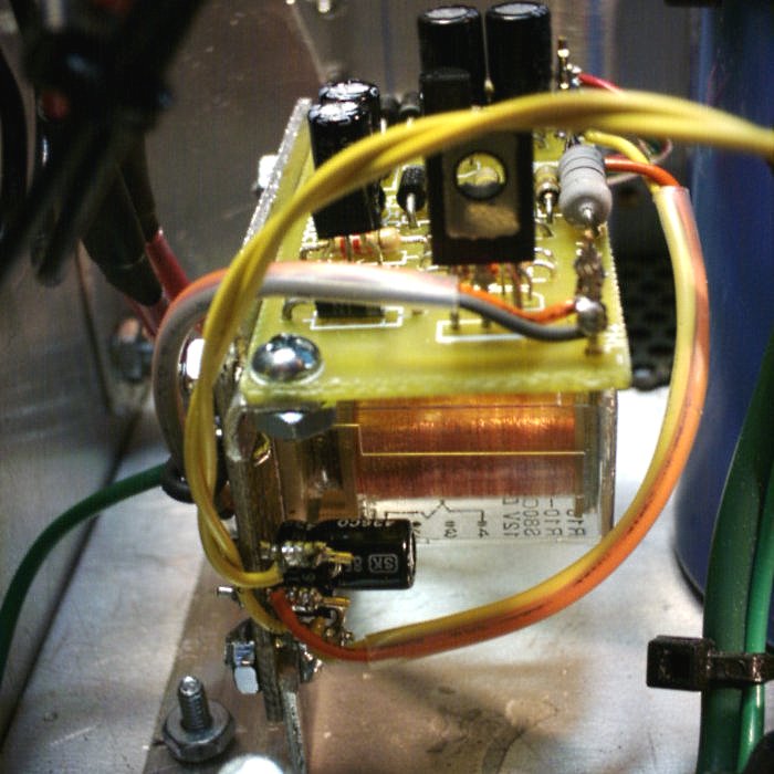
Figure 18. The isntalled muting relay assembly.
The P33 installation was the last step in completing all of the core hardware. The chassis was filled to capacity:
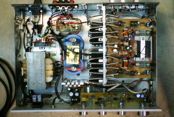
Figure 19. Overhead view of the assembled amplifier.
All that remained now was to see if I could get the wood chassis cover done right.
aaronv dot net -at- gmail dot com