Retro-1970s styling and power in a compact chassis.
The chassis had to be somewhat narrow. There was a Pioneer SA-7700 on my bench for repair around this same time, but I had previously measured it and found it to be about three inches too wide, and that was among the smaller options for suitable vintage equipment. So, what could I do with a substantial stock of aluminum? After more measurements and some careful thought regarding how the SA-7700 was constructed, this materialized:
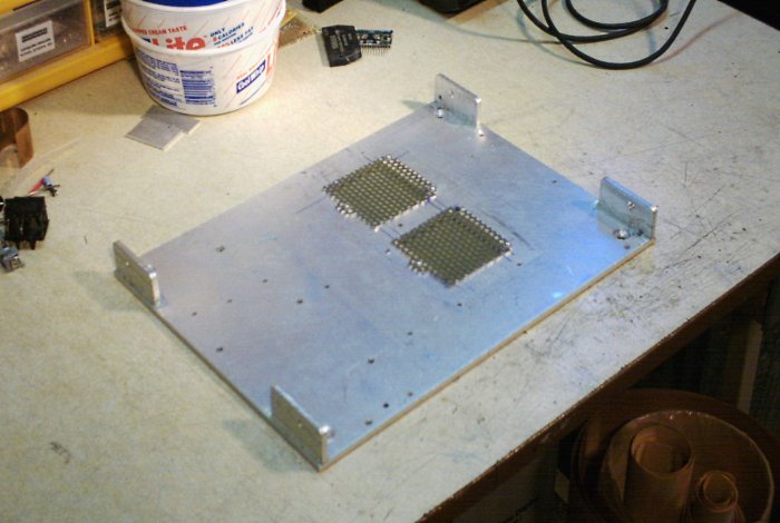
Figure 7. The chassis floor takes shape.
The vents will live directly under the heatsink area. The four risers are mounted from the bottom side with countersunk screws and epoxy. The base and risers are 1/4-inch (6.5mm) plate stock, cut from the same sheet that produced the heatsink and which would also supply a front panel.
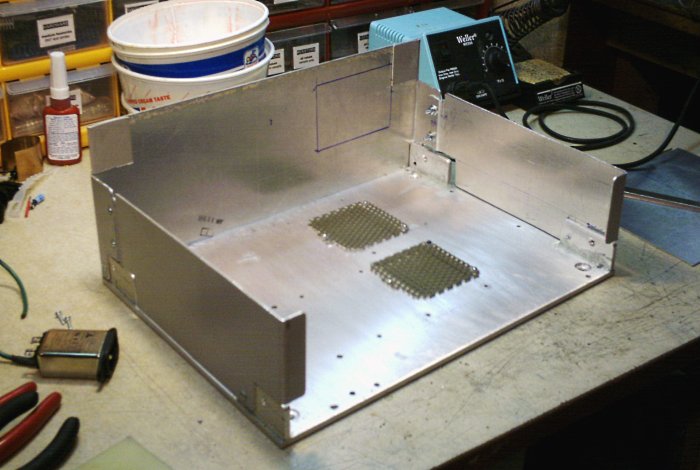
Figure 8. The chassis rear panel and sidewalls.
Next, a rear panel was required. I had also decided that a wooden 'C'-shell would cover the amplifier. That still left the question of how to mount the front face with minimal screws, brackets, or other unsightly things. I decided that two screws would be unavoidable, but the aesthetics could be handled by using oval-head stainless steel units. So, side panels arose with a pair of flaps on which to mount the face plate. The blue rectangle marks the approximate future location of the line input jacks. Skipping ahead for a moment:
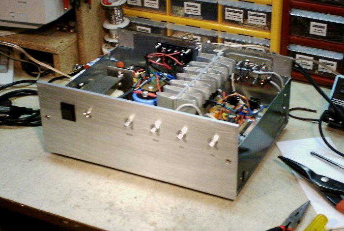
Figure 9. The completed chassis without the wood cover.
The above is a brief glimpse of the front panel and final assembly before the cover was installed. The front panel was given a brushed look by applying an oribtal power sander to remove surface imperfections, then given a slow, final application by hand with coarse-grit sandpaper. Once the desired look was achieved, the plate was washed to removed the aluminum powder, and the two screw holes were drilled, countersunk, and then beveled slightly by gently applying a very large bit with a drill press.
For a finishing touch, rub-on labels were applied for the preamp controls and the plate was sprayed with a clear matte laquer to secure the labels and preserve the metal against corrosion. Black screen printing and clear annodizing would be preferred but for DIY, this works well enough. If laquer were potentially too brittle, an automotive 2K (two-part epoxy) clear coat would be the next better option.
A power supply was required. In a modern DIY system the best answer would be a torroidal transformer to obtain the benefits of compact size, quiet operation, and low leakage flux. However, that wouldn't be in keeping with the 1970s design them, as low-cost, semi-automated torroid assembly had not yet been developed. The usual option in times past, even on higher end equipment, was a tightly constructed EI/frame type unit. Fortunately, I just happened to stumble across one at a surplus store I was haunting regularly at the time, and as a bonus, it had dual secondary taps at both 28V and 14V.
I never did find a rating for it but the physical size relative to output voltage suggested around 200VA. Between that and the dual taps, this thing had "integrated medium-power amplifier" written all over it.
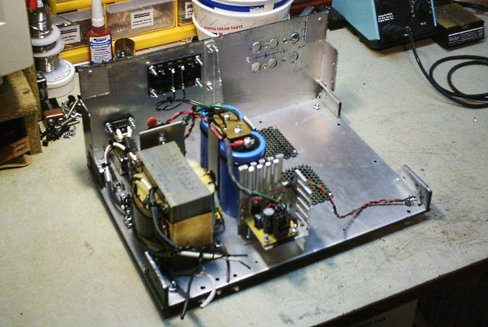
Figure 10. The newly-constrcuted amp, under test.
The copper belly-band did not exist on the unit when purchased. It was my own addition using scrap materials on hand. Although an EI cannot have its stray emissions eliminated except by encasing the entire unit in soft steel (a popular method in many higher-end vintage ampifiers and receivers), the belly band greatly reduces them by acting as a shorted turn in which stray emissions can be captured and dissipated as eddy currents.
The main filter capacitors are a pair of 11,000µF, 50V-rated units I acquired on eBay. The rectified DC peaks at just under 40V and a 10-20% margin is recommended on filter capacitor ratings, so these were ideal. A large U-bracket and a zip-tie holds them down to the chassis floor. Meanwhile, each pair of voltage taps feeds a separate bridge rectifier:
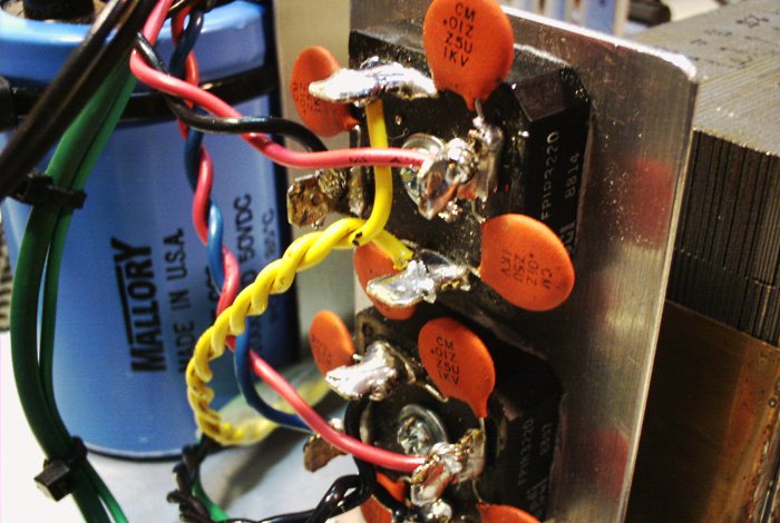
Figure 11. The bridge rectifiers.
The capacitor ring is an old trick for reducing RFI emissions, and will typically employ 10-100nF ceramic units. The theory is that when a diode is under heavy current loading, the sudden shut-off caused by the zero-crossings of an AC waveform can generate harmonics into the RFI range. This is more of a problem for stray emissions certifications in commercial equipment than for the amplifier itself, but it doesn't hurt to clean those out of the power supply and the method is cheap.
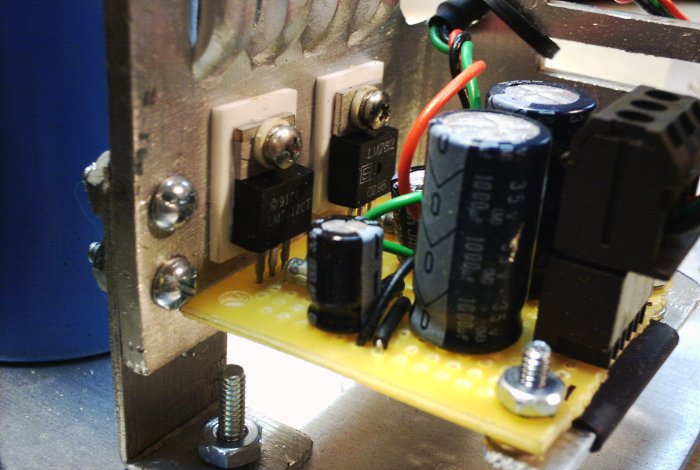
Figure 12. The low-voltage power supply.
The low-voltage supply is somewhat not in keeping with vintage traditions, since IC voltage regulators were not widely available back then. For an audio preamp the more likely method would have been a Zener voltage regulator directly feeding the preamp, or else driving the base of a pass transistor. On the other hand, quality op-amps were not widely available at the time, either, but that wasn't stopping me from using something more modern in my preamp board.
So, I proceeded with a simple LM7812/7912 regulator design. The heatsink is by no means necessary but I got it for free out of an old switching power supply and it has exactly the kind of elite overkill look that fit the look of this unit. I figured it ought to see a good home in a project like this, so there it is.
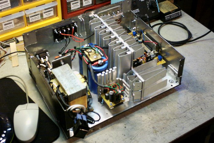
Figure 13. The amplifier installed.
The final task before moving into the preamp and final assembly work was to install the amplifier and its heatsink in the chassis, and then connect it to the power supply. Both the power and speaker wiring feed through the heatsink, rather than around it. Thus far the speaker wiring was fed directly to the outputs for testing purposes, but output relaying was planned and would be added later.
The main construction work was now finished. The amplifier was tested in raw state, and found to perform well. That being done, the next stage was to fill in the preamp and output relaying, then finish the case.
aaronv dot net -at- gmail dot com