Retro-1970s styling and power in a compact chassis.
My DIY inspiration included relics from my father's hobby, notably an imitation of the Bose 901 speaker kit. He built it around 1975 or so from a Popular Science magazine feature describing a knock-off cabinet and shaping equalizer, and the completed kit still lives today. For reasons of making the parts accessible to their readers and (probably) litigation avoidance, the writers deviated by specifying 8Ω drivers in a back-mounted, 3x3 series-parallel configuration and the equalizer wasn't quite as well designed as the Bose unit, one consequence being a tendency to blow out a transistor every five years or so. Dad later modified it for opamp use but all 18 drivers are original and continue to operate today.
Unfortunately, there were two issues. First, the 901 design has finicky room placement requirements for best output, and the placement for these units was non-ideal in every way. The second was a physical restriction on where the amplifier and equalizer could live. Three different mini shelf amplifiers were used over the years, with mediocre results.
Now, Dad thought maybe the age of the drivers and lousy room placement were responsible for the performance problems and was talking about retiring them for a pair of bookshelf speakers, but my ears were starting to understand the sound of clipping. I had a hunch I could do something about the problem on the amplifier side if I could make the requisite power fit within the available physical space. A full custom chassis was in order, but by now I had more experience and was ready for the challenge.
The power problem would be readily solved using modern audio hardware. Guesstimate calculations suggested the system both needed and could handle at least 30-40W/channel RMS, so the previous mini amplifiers were probably inadequate and overdriven by the shaping equalizer. I had recently turned up an obsolete STK3062III stereo input stage IC that looked like a fun project, and useful application schematics were located in a datasheet. I concocted a board layout, scrounged up the necessary aluminum bits, and bodged up a working stereo amplifier in a couple evenings:
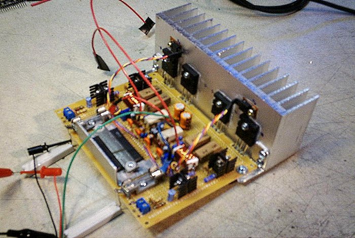
Figure 1. The newly-constructed amp, under test.
Per the Sanyo datasheet, the typical build for an STK3062III requires a pair of STK output stage ICs that are long gone from the market. But the very similar STK3042III included a datasheet schematic for a discrete output stage, and since I had a good transistor collection by this time, I gave it a try and it worked. The design doesn't save any parts over a fully-discrete amplifier build, but it does provide a stereo front-end with commendable noise and distortion characteristics. Also, the device is rated for up to ±48V continous and I was giving it about ±38V, which should improve the service life.
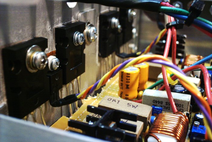
Figure 2. The amplifier's output stage.
The previous heatsink was too small (more on that in a moment), and was replaced. The final output stage mounting is shown above. The output devices are ON Semiconductor MJL4281A and MJL4302A. The TO-220 device is the bias servo. The output stage uses an emitter-follower (EF) topology and the servo must track the output stage temperature to prevent thermal runaway, hence the mounting on the heatsink, near the output devices.
In a commerical design the servo transistor is often a TO-92 type for cost savings, but a TO-126 or TO-220 case is easier to mount in a DIY design. Also non-typical are the output RC stabilizing pair, created by using a 5W resistor as both the high-frequency bypass and an inductor former. A commercial design might use an air-core coil and separate 2W resistor but this here is robust and adequate for DIY. A purist might insist on at least using a non-inductive resistor rather than a wirewound type but the effect of any low-value power resistor in the audio band should be negligible.
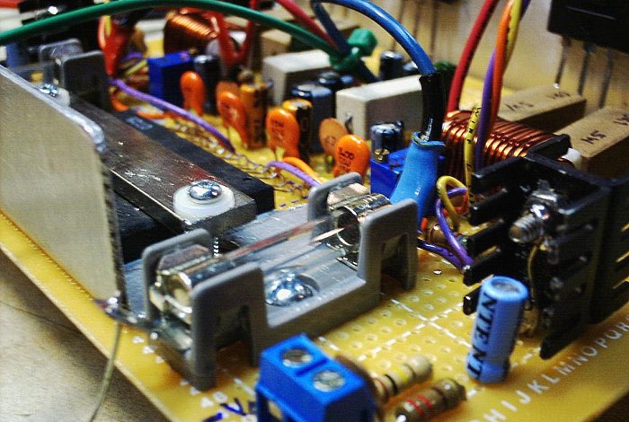
Figure 3. The amp, as viewed from the input section.
The STK3062III IC is mounted on a an L-shaped aluminum heatsink bracket. The doubled TO-220 heatsinks visible in the previous images are mounted to the output predrivers. It is more than they need, but why take chances? Within reason, too much heatsink is relatively cheap while too little is always expensive. And speaking of which...
Output transistor heatsinking was the next issue. My initial heatsink (see Figure 1) was a hair too small and the amplifier refused to thermally stabilize at any temperature I was willing to tolerate. I had already determined my chassis size and layout, so I either needed a fan (nope) or I needed something unconventional to make use of the available free space. The answer was a large piece of 1/4-inch (6.5mm) aluminum with custom fins:
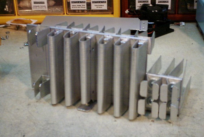
Figure 4. A fully customized heatsink design.
It may look like the unhappy offspring of a pipe organ and a microwave antenna, but it works and fills the usable space, creating not only a large dissipation area but also a partition shield for keeping power supply noise out of the amplifier zone. The L-shaped cut and the elongated fins are shaped around the mounting zone for the preamp board.
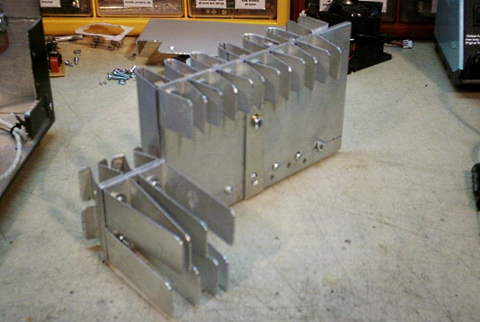
Figure 5. A face view of the custom heatsink.
For this to work, screw penetrations had to be kept out of the transistor mounting area. Fortunately a serach of an offcuts box turned up a length of predrilled bar with #6-32 tapped screw holes every 3/4" along its span. I cut it at suitable lengths and then used it to clamp the U-shaped chimney fins in place. The smaller U-fins elsewhere were secured using ordinary hardware, including fender washers to maximize thermal contact.
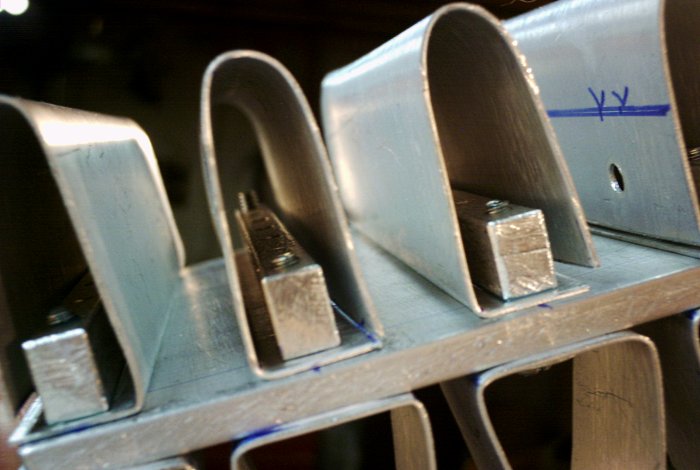
Figure 6. Vertical chimney fins held in place with strut bar.
The overall appearance is a bit rough and the labor requirements were absurd, but it works. The sink stabilizes at about 45-50C under normal loading conditions. Performance may degrade slightly over time as the thermal paste in the joints dries out, but the sink should be large enough to tolerate the aging process.
Next task: a fully customized chassis, capable of being sturdy while meeting the requisite physical space limitations. Oh, and it had to look good.
aaronv dot net -at- gmail dot com