or, How to Understand and Apply Circuit Protective Devices
APPLICATION
Given what we now know, how should a fuse or breaker be specified? The traditional approach is to use an available device rated at the nominal full load current, and then hope for the best. Some guesswork is unavoidable, but there are at least two ways to improve the odds.
First, we have seen that the fault current must be at least 200% (2.0 times) the fuse rating to ensure the upstream protection will cleanly trip, so the attached device must be capable of drawing it during a failure condition. Anything that limits the maximum fault current must be considered carefully. For example, if the supply is 24V and the circuit has a 10Ω source resistor in series with the supply, a perfect short circuit below the resistor is limited to:
I = V / R = 24V / 10Ω = 2.4A
Accounting for the factor of 2.0, the fuse cannot be rated higher than the nearest size to 1.2A. A standard 1.25A unit would be ideal...or would it? Another thing to consider is that if the fuse will take a few seconds to clear at exactly 2.0 times its rating, that might be enough time for the source resistor to heat up (it will be dissipating 2.4W), its resitance to increase, and the fault current to decrease a bit. In that case, we might round down just to be safe, and spec a 1A fuse.
Then again, take another look at the circuit. The designer may have specified the 10R resistor as the safety device, and while the circuit may suffer losses if a serious failure occurs, it won't fail catastrophically. But if there is any doubt, add the fuse.
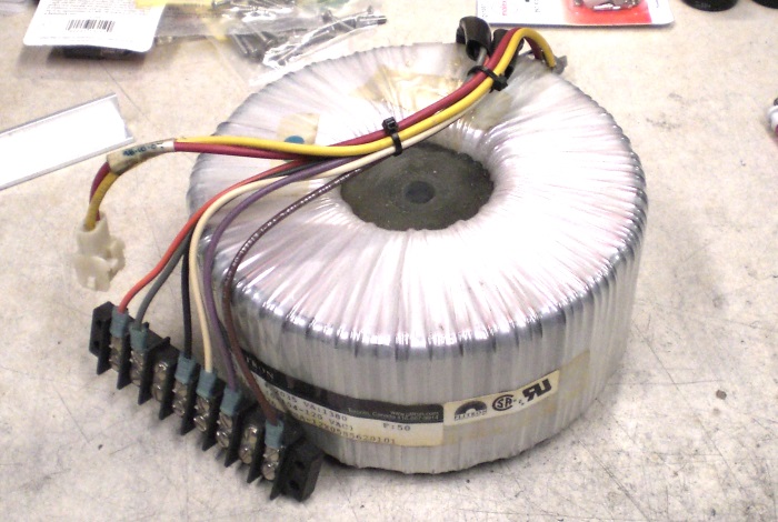
Figure 13. A device capable of limiting fault current.
The device shown in Figure 13, i.e. a transformer, throws a few other surprises at us. No transformer can supply unlimited fault current, and in simplified form, it looks a bit like a large impedance in series with our load. The principle is not so different from the 10Ω series resistor in the previous example, except we do not usually have the impedance printed on the label. Fortunately the transformer's impedance can be determined with a small selection of equipment that many DIY enthusiasts already own.
Transformer design is beyond this article's scope but we do need to know something about the short circuit test. The idea is to assume the transformer is a simple impedance element with an unknown R. Suppose we had a resistor that was missing its markings, but we did have a 12V power supply and an ammeter. The obvious thing is to briefly apply 12V to the resistor and then measure the current through it. If 1.2 A were measured, then:
R = V / I = 12V / 1.2A = 10Ω
The experiment is simple enough, although if the resistor had a very low power rating we might accidentally release the magic blue smoke rather than measure how much is in there. Something similar applies with transformers, which contain great volumes of magic smoke having the distinct odor of charred money. The maximum current may be far above our test capabilities anyway. Fortunately, we have data to determine how much current the transformer should be delivering in normal conditions, and if we can limit the current by controlling the input voltage, a methodology will emerge.
First, a strong caution: the transformer to be tested should be rated at least 40-50VA (EI types) or 25VA (toroidals). In general, if it is PCB-mounted, epoxy-potted, or small enough that it could be, don't even bother. Very small transformers, especially miniature EI types, have very fine windings and operate near or at saturation regardless of load. That reduces costs but also means the standard failure mode is burnout, since the maximum output fault is only slightly above nominal full-load and a practical overcurrent fuse cannot be provided. A source fuse should still be used as it will protect the rest of the system from high side failures, but the transformer should not be short-circuit tested.
Required hardware to perform the short-circuit test includes:
Variable autotransformer (Variac) Two multimeters, at least one having an AC ammeter function Test jumpers, terminal blocks, or similar A transformer to be tested A calculator
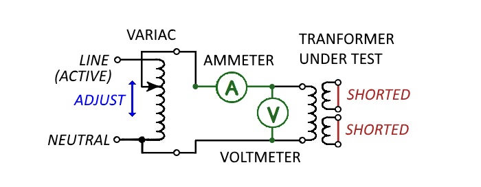
Figure 14. A schematic of the short-circuit test.
Ideally both multimeters will have true-RMS capability, but if not, a ballpark figure can still be obtained. The hardware will be arranged according to Figure 14, except the calculator, which remains firmly in hand. First, determine the transformer's full-load current, IFL, for the primary winding(s) by taking the VA and dividing by the full winding voltage. For example, suppose we have a 300VA transformer and a 120V primary:
IFL = VA / V = 300VA / 120V = 2.5A
The approach still works even if we have multiple windings; what matters is that we connect all of them in order to utilize the full transformer VA, and then account for the full series or parallel voltage applied to the unit when we run the math. Two 120V windings on the primary of a 300VA unit, connected in parallel, are still 120V, 300VA, and 2.5A full-load current. On the other hand, if this is a 240V system and we connect those two 120V windings in series, the full-load current on our primary is now 1.25A by the same method.
The short-circuit test can be run on primary or secondary, but for our purposes here, we are shorting the secondary using test leads or terminal blocks, and testing the primary with meters connected. Small control voltage windings, if present, will contribute little to the test results and could overheat during the test routine. These should be left floating, but all power windings must be included in the test.
Run the test like this:
1. Set the Variac to 0V before connecting power. (Insert giant blinking DANGER lights here.)
2. Switch on the meters and verify both are correctly configured for voltage and current, respectively.
3. Connect power and watch the ammeter closely as the next step proceeds.
4. Slowly ramp the Variac until current flowing into the primary equals IFL.
5. Take note of voltage VSC measured across the primary.
6. Shut down the test kit and warm up the calculator.
Normally this test would be temperature-corrected at a standard ambient to account for the imepdance change that occurs as the unit heats. But most of us do not have sufficiently precise equipment to make much difference, and our results will be close enough to be useful. To determine the short circuit impedance, simply divide the short circuit voltage into the full-load current. For our 300VA transformer, if the applied voltage in the short-circuit test was 12V on the 120V winding when 2.5A were flowing, then the short circuit impedance would be:
RSC = VSC / IFL = 12V / 2.5A = 4.8Ω
The result is sometimes designated by Z rather than R since the impedance contains both resistive and reactive components. It may also be expressed as a percent by dividing VSC by VNOM. For simple current calculations, it can be understood and used like R in Ohm�s Law. Now divide VNOM by the impedance and we have the absolute maximum primary current that will flow for a worst-case short circuit on the secondary side:
ISC-PRI = VNOM / RSC = 120V / 4.8Ω = 25A
The plain meaning is that we can bypass the load center breaker at our source (don't, please) and tie the secondary windings to gold-plated, oxygen-free, moondust-infused copper bus bars of the highest audiophile grade, yet no more than about 25A will flow into the high side until the transformer's internal thermal fuse permanently ends our fun. That has implications on the largest fuse or circuit breaker we can specify on the high side of the transformer. Using what we now know, we can say that it needs to be at least twice our full load current (2.5A), but less than half our worst-case short circuit current (25A). In other words, somewhere between 5A and 12.5A, and we want to leave a bit of margin. Something like a 6.25A or 7A slow-blow fuse should fit nicely and be in stock at the supply house.
The principle of V-I conversion across a transformer ratio still applies to a through-fault current, so we can use the turns ratio (which is also the voltage ratio) to calculate maximum fault current on the low side. Supposing our 120V, 300VA transformer had dual 24V secondaries, connected in series to create a nice symmetrical supply for a new 100W/channel amplifier project. Our worst case fault current on the low side is:
ISC-SEC = ISC-PRI * VPRI / VSEC = 25A * 120V / 48V = 62.5A
That's quite a bit more, and reliable tripping is less likely to be a problem for low-side devices. It also suggests we should not be relying on the high-side fuse to protect low-side equipment. In practice, two other factors will limit our current into a short circuit. First, the upstream connection back to the load center and power provider equipment probably adds another 2Ω to our net short-circuit impedance. Second, high-power faults will drive the transformer into saturation, capping its maximum sustained fault current at some value below the theoretical maximum.
In short (haha), we can calculate theoretical values, but given the unknowns, it's better to err low on fuse or breaker values. A device failing on the low side can flare up or be blown to bits before a fuse on the high side decides to trip, and the fault current we are using to trip a fuse on either side may be unpredictably lower than our worst-case calculation.
What results could be expected for real transformers used in hobby projects? A sample of toroidal types from my own collection follows in Table 1. These also were measured at about a 20C ambient and are not temperature corrected, but for our purposes here they will suffice.
| Manufacturer | Model | Pri-1 (V) | Pri-2 (V) | Sec-1 (V) | Sec-2 (V) | Pwr (VA) | IFL (PRI,A) | VSC (PRI,V) | RSC (PRI,Ω) |
| Antek, Inc. | #AN-0212 | 115 | 115 | 12 | 12 | 20 | 0.1739 | 9.84 | 56.6 |
| Antek, Inc. | #AN-0512 | 115 | 115 | 12 | 12 | 50 | 0.4348 | 10.70 | 24.6 |
| Antek, Inc. | #AN-1225 | 115 | 115 | 25 | 25 | 100 | 0.8696 | 8.77 | 10.1 |
| Amveco Mag. | #AA-28263 | 120 | - | 57 | CT | 288 | 2.4000 | 7.29 | 3.03 |
| Amveco Mag. | #AA-28263 | 120 | - | 57 | CT | 288 | 2.4000 | 7.33 | 3.05 |
| ILP Mfg. | #49783R1-1014 | 120 | - | 24 | 24 | 160 | 1.3333 | 9.71 | 7.28 |
| Toroid of MD | #4230 | 115 | 115 | 18 | 18 | 100 | 0.8696 | 5.85 | 6.72 |
The two Amveco units are of some interest, since both have identical part numbers and ratings. As expected, the measured impedances are very close, but manufacturing variances are also real. In this case the difference is small, but that is not inevitable. A lesser-quality design, or two units manufactured across a raw materials change-out on the same line, or two units manufactured on parallel production lines, could show more deviation. Toroidal transformers, in particular, required full or partial hand-winding until within the past couple decades, so older units (i.e., the kind most likely to show up cheap at surplus sales and in scrap equipment) may show more variation for that reason alone.
As another interesting point, compare the two EI (frame) type units of Figure 15.
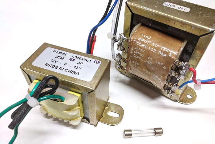
Figure 15. Two EI transformers with a 3AG-type fuse for scale.
In the above, both units are targeting 110-120V systems on primary and output low voltage on secondary, yet the smaller unit at left is actually a 72VA unit while the noticeably larger unit at right is just 48VA. Part of the difference is explained by the second unit being around 30 years old and over-designed, while the first unit is new and almost certainly optimized using modern CAD/CAE tools. However, there is clearly more core steel in the second unit, and the short circuit test bears it out. The 72VA unit at left tested at just 2.9%, while the 50VA unit at right tested 7.7%.
Neither design is right or wrong, but the additional core steel in the second unit contributes to a higher inductance and resulting higher short-circuit impedance. It will also show more voltage collapse on the secondary under heavy load.
Plug packs have not yet been addressed in this article. A brief discussion will follow, and then we can wrap up everything with a summary and conclusion.
aaronv dot net -at- gmail dot com