or, How to Understand and Apply Circuit Protective Devices
EXPERIMENTAL: BREAKERS
To get a proper handle on all this, a selection of fuses and circuit breakers were tested. Test kit included a true-RMS meter as the AC ammeter, a second meter for AC voltage, an 8Ω dummy load, and a 500VA variable autotransformer (variac). An isolation transformer was also used for safety. The result was a cheap and cheerful way of delivering a controlled current through a test device: adjust the voltage to a target setpoint while looping the output through the dummy load. Ohm's Law takes over from there while the meters confirm its results.
For circuit breaker tests, one device of each type was used and multiple trips were run and averaged. Thermal devices were cooled between test cycles. Current ratings for all were selected per the 7A limit of the test kit.
For fuse tests, a parallel LED was connected across the test unit to give visual indication of failure. A simple stopwatch was employed to measure trip times. Not precise, but for these tests the trip was either instantaneous or averaged out somewhere from a few seconds to several minutes, so it was close enough to prove the point. Several fuse types and ratings were tested as a consistency check but only 3A Fast and 3A Time Delayed fuses are presented here, and 40 units (four of each type, at five diferrent current thresholds) were tested to produce an average data set. Surviving fuses were not reused.
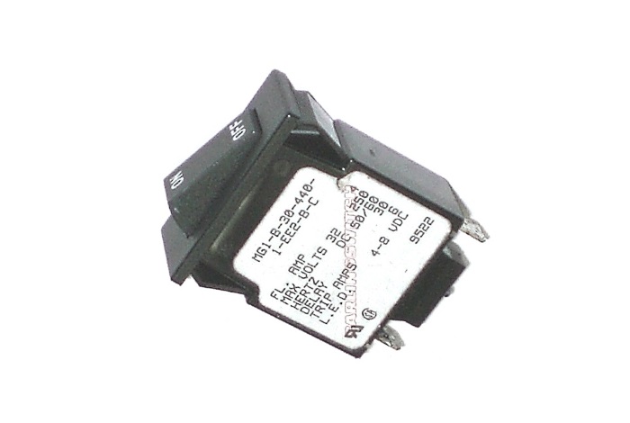
Figure 7. A 4A magnetic-element breaker with useful spec info printed on side.
The device in Figure 7 has useful design information provided on the label, which is where we prefer to find it. Among other things, this unit has a 32VDC or 250VAC (50Hz or 60Hz) voltage rating, a 4A maximum continous rating, and is guaranteed to trip at 6A maximum with a delay of "30" (cycles, i.e. about 0.5 seconds).
In practical testing, it permitted about 4.25A to pass through continously before tripping. This unit might survive a higher transformer inrush on account of the 30-cycle trip delay, but would be very intolerant of any momentary overload even though the transformer would be fine with it.
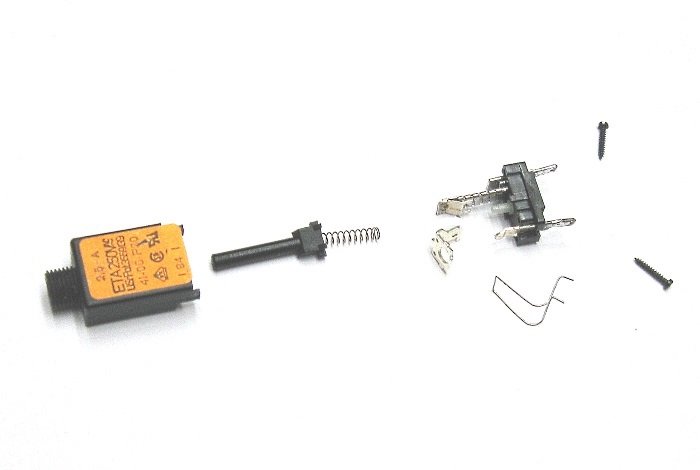
Figure 8. A 2.5A thermal-element breaker, exploded view.
The thermal breaker of Figure 8 the represents the pushbutton type, using a heating element to warp the bimetallic strip and release a catch. Two springs are involved: one to tension the catch and a second to load up the pushbutton. The label only indicates a 2.5A current rating, the vendor, and a smattering of other data. While it would be nice to have more specifications on the label, we can typically use the vendor and part number to locate specifications. Unfortunatley, this unit is obsolete, so although E-T-A is still in business, the data are not published. In such case an information request to customer service may yield results, but that effort was beyond our testing needs.
The 2.5A unit was not tested but an identical 500mA unit was run through the paces. Two intereseting results emerged. First, the 500mA unit had a cold resistance of 3.4Ω, which appeared to rise further at the load limit. That would shave at least 2V off the supply potential at 500mA, a troublesome tic for any low-voltage uses. Second, at 0.75A or 150% of nominal, the breaker required about one minute to release. At 1A or 200% of nominal, the trip time was 14 seconds. The unit required 1-2 seconds to release at 4A and was still delayed by nearly one second at 5.5A. While this behavior is not typical for all thermal circuit breakers, the observed results reflect the danger of relying on devices with unknown specifications if precise results are required.
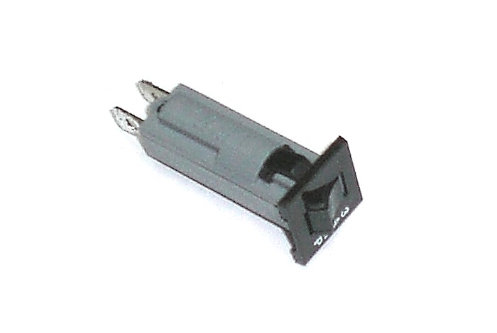
Figure 9. A 3A thermal-element breaker, fuse-replacement style.
The device of Figure 9 is a retrofit-capable replacement for a panel-mount, 3AG-style fuse holder. Like the previous thermal breaker, it is a pushbutton reset type without a user-selectable "off" position. Unlike the previous device, this one specifies a through-resistance of just 0.069Ω, which was confirmed using a high-precision bench meter.
At 3.75A, or 125% of nominal, the device produced a range of clearing times from 82 to 122 seconds, with an average of 101 seconds. Increasing the current slightly to 4A (133%) produced more reliable tripping, as the average time dropped to 51 seconds with reduced spread. At 4.5A (150%) and 5.25A (175%), the respective average clearing times reduced to 17 seconds and nine seconds, and at 6.0A (200%) a consistent five-second clearing was obtained. Slow-ish but consistent performance at 200% of nominal means this device is a very good substitute for a time-delay fuse.
EXPERIMENTAL: FUSES
Two 3AG-style models with a 3A rating were given the full abuse: CQ-ADL, a time delayed type, and CQ-AFE, designed for fast operation. Units were tested at continuous currents of 3.75, 4.00, 4.50, 5.25, and 6.00A. Four new, unused units of each type were tested at each current level (40 units total) and the results were averaged.

Figure 10. A sample of the carnage.
At 3.75A, no failure occurred in either fuse type, even when the test was extended out to 20 minutes. The fuse element deformed and the current dropped slightly as clear evidence of heating, but the current finally stabilized indicating a steady-state condition was achieved. We can assume a stress failure would eventually occur after repeated cyclings at this condition but the circuit would not be protected.
At 4.00A, type ADL required anywhere from 7-13 minutes to fail, and type AFE failed in a bit less than five and a half minutes. A real-world circuit would eventually be disconnected but no portion of the attached device would be reliably protected from damage.
At 4.50A, clearing times dropped dramatically for both fuses, to 01:43 (AFL) and 00:30 (AFE). A reasonably-sized power transformer would be protected against sustained overload by either fuse, although a sensitive small-signal circuit feeding from the transformer would not be protected. At 5.25A, clearing times reduced further to 50 seconds (AFL) and 6.3 seconds (AFE), and 6.00A produced 16.75 seconds (AFL) and 0.5 seconds (AFE). The circuit is now protected to the greatest extent practical.
Either dataset can be estimated graphically as a TCC, although note that the scales in Figure�11 and Figure�12 are not logarithmic as would otherwise be typical in vendor documents:
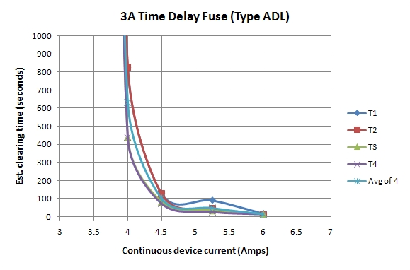
Figure 11. A compiled 3A, type ADL, time-delay fuse TCC.
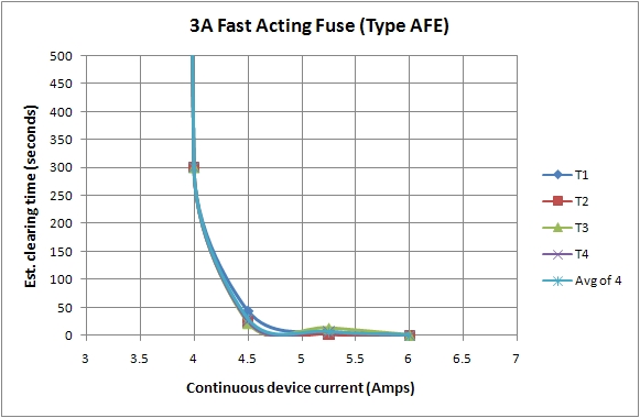
Figure 12. A compiled 3A, type AFE, fast-operate fuse TCC.
Both curves look very similar due to a lack of a logarithmic scale, which could not be accurately measured or plotted without high-speed test equipment and a much larger sample size. Regardless, note that the fast-fuse scale is 500 seconds on the time axis versus 1000 seconds for the time-delayed type, and the much wider spread of the time-delay unit curves is an expected behavior. At the very least, the results convincingly demonstrate that a circuit can only be reliably protected when the available fault current is at least twice the nominal fuse rating.
Now that experimental evidence has reinforced the theory, we need to look into how to apply it. Transformers, in particular, present an additional protection challenge that requires a detailed explanation.
aaronv dot net -at- gmail dot com