or, How to Understand and Apply Circuit Protective Devices
Note: A previous version of this article, with additional comments by Rod Elliot, appears on the Elliot Sound Products website. My thanks to Rod for his support in bringing the original article to completion, without which this revised version also would not exist. -aaronv, 2018-12-12
INTRODUCTION
Fuses and similar circuit protectors are one of the most-applied devices in hobby projects, yet among the least understood. On one hand the current rating is obvious enough, and a general description of "fast" or "slow" is sometimes given. But there are also nuisance trips and equipment that releases the magic blue smoke before the fuse blows, and many hobbyists are resigned to specifying circuit protection with best-guess, prayer, and a supply of spares.
A better approach is within reach. The goal here is to understand what several common circuit-protection devices are really doing, how they do it, and recognize other circuit elements might affect their behavior. With those factors in mind we can reduce the number of assumptions and have more confidence that our circuits are reasonably protected.
In many electrical circuits power is supplied by voltage control. A reasonably constant voltage is applied, and the load has some sort of impedance, often expressed as R, but sometimes referred to as Z to represent a complex impedance having both resistance and reactance. Current then flows through the load according to Ohm's Law, V = I * R, where V is potential in Volts, I is current in Amps, and R is the impedance in Ohms.
Solve Ohms' Law for current and the result is I = V / R. All is well in the land of I if the load operates correctly, but if a fault occurs (i.e. a failure condition, such as short-circuit), this same equation shows that as resistance decreases to zero, the current through that fault increases to an infinite value regardless of the voltage.
No real-world fault is ever 0Ω and no power source can support unlimited current. The supply voltage will tend to collapse under these conditions, too. Even so the resulting fault power may be quite sufficient to blow off your eyebrows, and maybe a few more of your handsome features, on its way to burning down the equipment, the supporting furniture, and anything else capable of rapid oxidation. The source must be automatically interrupted before that process goes to completion.
FUSES
The fuse is a very old form of protective device. If too much current can coax a circuit wire into becoming a toaster, then maybe a smaller, expendable wire can be placed at the front of the circuit where it will melt first. Et voilà, the fusisble element, or fuse, used in everything from tiny electronics to high voltage power systems. A fuse is a one-shot device and prefers to live in a case or cartridge that can be quickly refurbished or replaced after a failure.
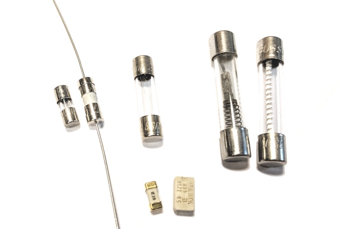
Figure 1. Common fuses at 250V or less (from left): two subminiature fast, a 5x20mm miniature fast,
two 3AG-style (1/4"x3") miniature with time-delay elements, and (lower) two surface-mount fast.
The tricky part is this: the fuse must pass normal currents without nannying the flow, but when a fault occurs, it must fail heroically. Fortunately, the power expression of P = V * I, where P is the power in Watts, works in our favor. Substitute algebraically with Ohm's Law and we can rewrite it as P = I2 * R, showing that a linear change in current produces an exponential change in power dissipation, which is useful for tuning the fuse's internal design to meet these goals.
But, how quickly should the fuse fail? Fast, slow, and by whose stopwatch? How much current must flow before it actually fails? Every element has manufacturing tolerances, so a Time-Current Curve (TCC) is provided as a visual summary. A logarithmic scale is typical, with current shown on the horizontal (x) axis and time on the vertical (y) axis.
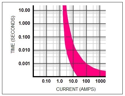
Figure 2. Possible TCC for a 1A, fast-acting fuse.
Figure 2 illustrates a hypothetical, very fast, 1A device. The horizontal (y-axis) width of the TCC represents a normal range of failures that would be observed in actual devices. For a given current, no device can be guaranteed to fail at one precise time but it can be guaranteed to fail within a known statistical range.
First, we see that no fuse of this type will reliably melt until at least 1.5A are flowing through it, and some may not fail until 2.0A are flowing. At those levels, the failure may take around 10 seconds to occur, although an aggressive unit may open the circuit two or three orders of magnitude faster. Note that the minimum pickup must start somewhere noticably higher than the rated load else nuisance failures will be a problem. Here we are showing a minimum pickup of 150% and a maximum of 200%, although it is common for real-world fuses to have a minimum pickup start at 200%.
Second, we see that as the current increases significantly beyond the minimum trip, the failure of any fuse becomes effectively instantaneous. That result is not too surprising, as the fuse effectively becomes a single-use flash bulb.
The TCC characteristic applies to an entire family of fuses. If I were to develop and sell this fuse as "Type AV," then all Type AV fuses would have this same curve shape, and it would simply shift to the right or left depending on the fuse current rating. A 10A fuse of Type AV might have a minimum and maximum pickup spanning about 15-20A at the top of the plot but otherwise follow the same statistical spread of failures.
For any fuse application, three datapoints are particularly useful to a DIY builder:
Timing Characteristic. Smaller fuse styles may specify �fast acting� (FA) or �slow blow/time delay� (SB or TD) while the TCC is buried deep in the manufacturer's product literature. Fast fuses are intended for applications where any failure condition must be quickly interrupted. Time delay fuses are useful when a momentary overload may legitimately exist, such as motor or transformer startup.
Voltage Rating. As a fusing element separates under load, an arc can strike in the gap and current flows through the arc until it quenches. Sometimes a fuse will be either sand-packed or spring-loaded to speed things up. In any case, the voltage rating specifies the maximum voltage for which clearing is guaranteed. AC ratings are usually higher than DC ratings since the AC zero-crossings help quench the arc. Smaller cartridge and blade fuses for household appliances and automotive use commonly have a 250VAC and 32VDC rating.
Current Rating. The nominal rating is the maximum continous load current. Generally, a fuse has a long life at normal loads and fails reliably during a fault. But an under-rated fuse may suffer nuisance failure in normal operation, while an over-rated fuse is just another wire in the circuit and will protect poorly, if at all.
At this point one quickly wishes that the product literature were more accessible than in reality. Mergers and acquisitions among major US and Eureopan electrical vendors have been astounding over the past two or three decades, with attendant disorder in the product libraries. Japanese and Korean equipment often follows traditional western standards but has its own unique cataloging systems and similar problems with documentation getting lost amidst mergers and spinoffs. Indian products are often documented better by oral tradition than anything committed to writing, and Chinese vendors have been proliferating exponentially through an admixture of blatant copying and genuine innovation that defies either a proper analysis or a cataloging effort. In all cases a too-common effect is that product literature can be buried at archaeological depths in the company website, if even available.
Sometimes a better approach is to find online resellers of equipment and see what they have archived. But in any case, if the above three items - timing (fast or slow), voltage (VAC or VDC), and current (Amps) - can be identified from packaging or found on the physical device, then we do have enough data to make a reasonable selection. The particulars will be examined a little later.
Why do nuisance failures occur? One obvious cause is a fuse incorrectly specified for the circuit. Overloading is a clear antagonist, and another is a fast fuse installed where a delayed type is needed. In glass-cartridge fuses, a stressed element can sometimes be observed to deform during overload conditions. It may survive a number of cycles while doing that but it will eventually fail. A fuse aged by numerous operation cycles can also die randomly. Mechanical vibration is an aggravating factor in kit that is physically moved during operation or contains moving parts.
Fatigue from aging is normal but frequent failures can indicate some other equipment design problem or an intermittent fault. If a fuse needs regular changes, then the type and rating, and the connected circuits or equipment, should be examined for problems.
A few other variations can be discussed briefly. Blade-style fuses of varying sizes are common in automotive applications, along with plug-in fuse blocks for high-current circuits. These generally have a 32VDC rating and no AC rating is specified. In-line blade fuse holders can be used for some types of automotive hobby projects, but there are better options for managing mains voltage.
In cartridge fuses, there is another design variation known as the current limiting fuse (CLF). A CLF cartridge often has special knurl at one end that fits into a rejection clip, which will accept the CLF but spit out a conventional fuse. CLF types exist but are are uncommon in the 250VAC styles favored by DIY enthusiasts. Some electronic applications do use a fusible resistor as a type of CLF, since it is designed to fail in an overheat without spitting smoke and flames.
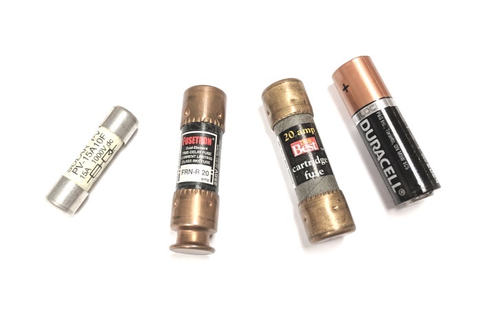
Figure 3. Other fuses (from left): 10x40mm 1kVDC for photovoltaic use (twice the size of a 5x20mm),
Class H 600V CLF and standard (both 25x75mm), and size-AA (UM3) battery cell for scale.
Note that for historical reasons, appliances in the United Kingdom require plug fuses in nearly everything to protect the upstream circuit from local failures that may not be reliably detected by the mains load center (look up the UK ring circuit on the Internet for details). In North America (and perhaps elsewhere), fused plugs are less common and tend to be required only in devices that can be sequentially connected to create truly spectacular overloads or are connected with ungrounded plugs outdoors, such as holiday light strings and related decorations.
THERMAL FUSES
We won't spend much time on this animal since it has very few DIY applications. It is worth knowing that it exists and it fails by thermal melting, but the element is designed to fail at a specified temperature primarily by external heating and does not provide reliable overcurrent protection. The usual habitat is a water tank, hotplate, or sidewall in a heating-element appliance. If the appliance breaks free of its thermostat leash and attempts uncontrolled entropy, the thermal fuse will fail and disable the device's power supply, saving the fire brigade the trouble of doing it the old fashioned way.
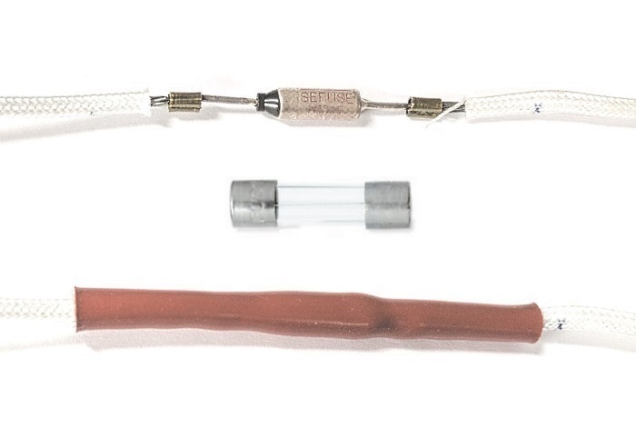
Figure 4. Live-body thermal fuse, exposed (top) and sleeved (bottom). The
device is slightly smaller than a 5x20mm cartridge fuse (center).
The device in Figure 4 was formerly attached to a single-serve coffee brewer's internal tank, but since that unit had provided many years of faithful service in an office staffed by caffeine addicts and had died of exhaustion, it was subjected to autopsy by my curiosity and screwdriver. Thermal fuses of this type have a live body and operate in high temperature environments, requiring a tube of durable silicone or a special rubberized electrical insulation. Correspondingly they can be quite dangerous if mishandled.
aaronv dot net -at- gmail dot com