One very big boom in an unexpectedly small package.
Page 1 | Page 2 | Page 3 | Page 4 | Page 5
I had an amplifier but needed somewhere to mount it. A typical subwoofer uses a plate amplifier, referring to the fact that all electronics and power supply kit are attached to the backplate, keeping the driver, cabinet, and eletronics separated into three discrete pieces. My setup was a bit more elaborate and permitted ventilation, but I still needed a plate for the amplifier, controls, and external amplifier heatsink.
Fortunately, a former college roommate's father was a self-employed machinist at that time, and had several nifty toys including a CNC laser table. I sent him the following drawing and asked if it was possible to cut it from 1/4-inch aluminum stock:
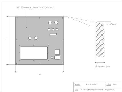
Figure 16. A preliminary drawing of the plate.
He took a look, said it might, but if not, it would definitely work with 1/8-inch steel. I then sent three more drawings, not quite to scale, but with all cutouts plainly dimensioned.
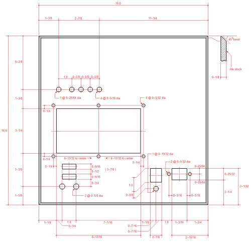
Figure 17. Plate dimensions: primary cutouts.
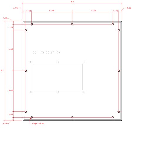
Figure 18. Plate dimensions: permiter mounting holes.
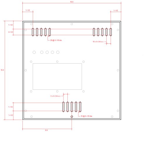
Figure 19. Plate dimensions: ventilation slots.
He redrew the plate in AutoCAD and sent it to his father for inspection. Verdict: the laser would blow out aluminum due to the close hole spacing, so it would have to be steel. The other limitation was that avaialble shop machinery could not create the beveled edge, so the corners were rounded instead.
The completed plate drawings was as follows:
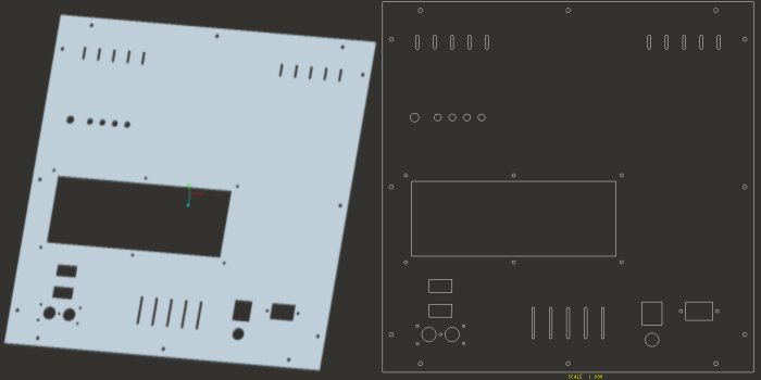
Figure 20. CAD drawings of the completed plate.
The last step before committing the design to metal was to verify rear clearances. I printed the drawing at 1:1 scale, cut out the major holes, and attached it to the box. It was tedious work, but as the saying goes, measure twice and cut once. I was begging a huge favor here, so I didn't want to approve it, install the plate, and then discover critical spacing issues. Everything looked good, so I greenlighted the design and waited.
Finally, it arrived! Two coats of paint, some lettering work, and a clearcoat later...and the plate was ready for final assembly:
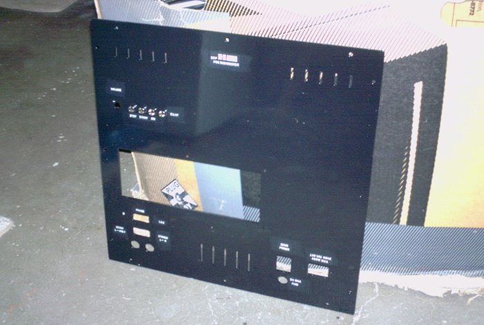
Figure 21. The plate is ready for final assembly.
One curious spider can make a big mess, so I cut out a few small squares of window screen, gave them a quick coat of black paint, and glued them over the rear side of the vent holes using quick-set epoxy.
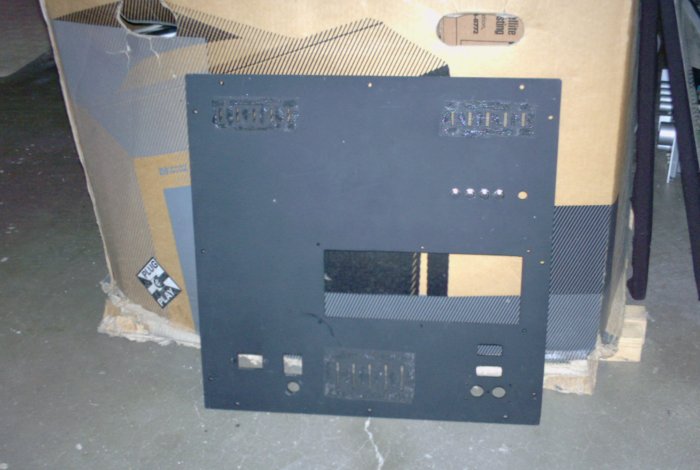
Figure 22. Screen patches cover the ventilation slots.
With that out of the way, and the subwoofer having been successfully tested with the amp bare-mounted on its heatsink, it was time to put the thing together.
In retrospect, my design approach left too much coiled wire in the chassis, but it worked anyway:
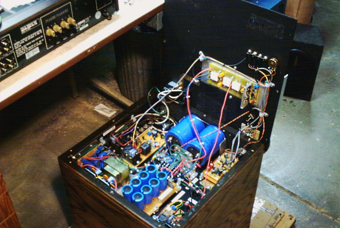
Figure 23. The plate has been completely assembled.
The amplifier is bolted directly to the heatsink, while the heatsink overlaps the plate and mounts to it via six screws.
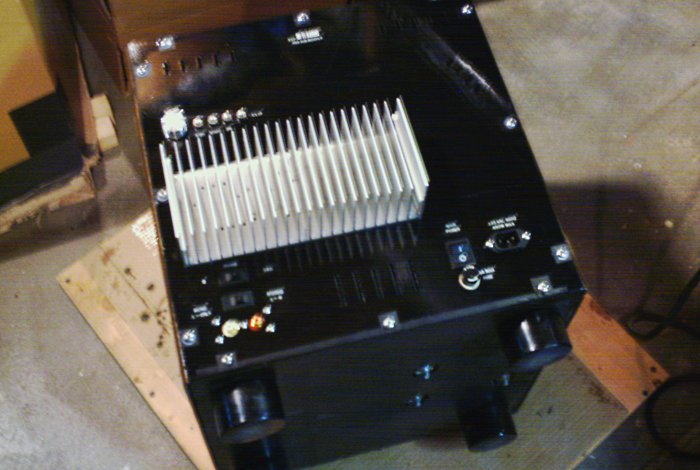
Figure 24. The plate, installed on the cabinet.
And there it is! The level control knob and indicator LEDs are located above the heatsink. The phase and Stereo/Mono switches, and the line input jacks, are located below the heatsink. At lower right are the IEC-style input jack, master power switch, and master fuse holder.
aaronv dot net -at- gmail dot com