One very big boom in an unexpectedly small package.
After running a few general tests of the equipment, and confirming all was well, it was time to purchase and assemble the amplifier. And here it is:
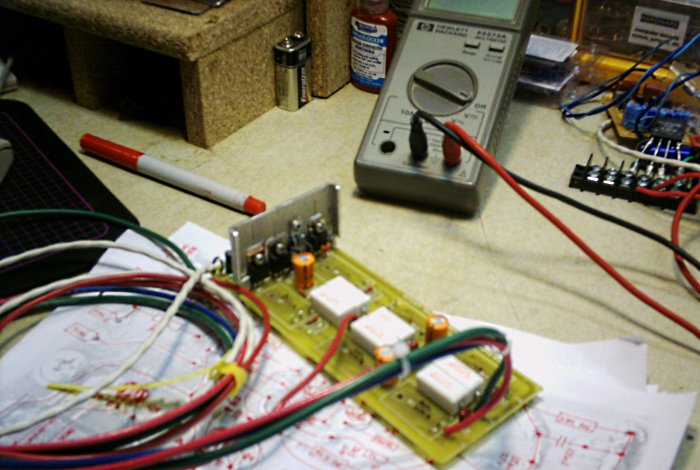
Figure 9. The assmembeld amplifier, with TO-220 devices installed exactly backwards.
In theory, this was a working amplifier, but in fact it had a rail-sticking problem. Rail sticking is a condition where the output, instead of centering at 0V, is driven to either the positive or negative voltage. The result was three frustrating weeks of periodic troubleshooting.
It turned out that the P68 board was originally designed for the three devices on top to be TO-126, while a TO-220 recommendation came later. In one of the electronics industry's inexplicable conventions, these two have exactly opposite pinouts, so while the center pin (base) was in the correct hole, the emitter and collector were swapped. In fairness, I had little experience with active devices at the time and the instructions (since revised) did not account for it.
What finally turned up the problem was when I scanned the PCB traces (this was in 2005, these days any mobile device camera works great), flipped it and printed it in low-contrast black and white, and began drawing the schematic of the circuit from the top side as though I were looking through the board with nifty x-ray vision. As soon as I labeled pins on the transistors the problem was obvious. The devices and heatsink were subsequently reversed to correct orientation, and the amplifier promptly passed a ±12V stability test followed by a ±30V test with a light load.
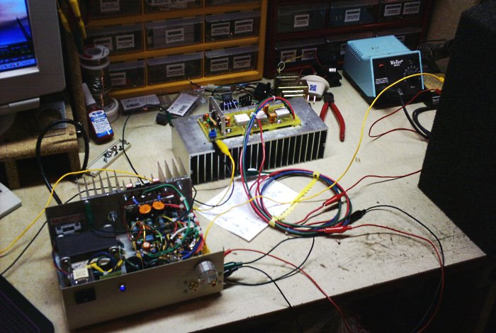
Figure 10. The assmembeld amplifier running at +/-30V rails.
The ±30V power supply is, in fact, the P03 amplifier which I built midway through the subwoofer project for exactly this purpose. The P03 is disconnected from DC at a terminal block. The P68 is powered by the supply and accepting an audio source from the computer, while driving a boxed 4Ω car speaker on the right.
The upshot was, I learned a useful technique for troubleshooting circuits. I have since used the "picture, flip, print, and trace" technique on several occasions to replicate and enlarge PCB layouts. It is useful for working out bugs on DIY projects, and even more valuable for reverse-enineering schematic diagrams when repairing commercial equipment.
With the amp up and running, the next thing needed was a driver. As noted earlier, I originally had aspirations of buying an Infinity Perfect driver. These aspirations whithered and died when I realized that both the 10" or 12" unit cost about two or three times my practical budget. With that idea disappointed, I prowled a local car audio shop to see what my local options might be. And then returned home with this minor sesimic disturbance:
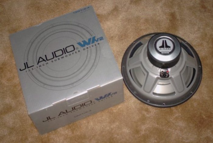
Figure 11. Subwoofer driver by JL Audio.
Meet the JL Audio 13W1/V2 13.5" (345mm) subwoofer driver in 4Ω form. The unusual diameter was what sold me on it. I had no expectation of finding a driver larger than 12" locally. Volumetrically, a 13.5" moves quite a bit more air than a 12" unit, which is only good news for an equalized subwoofer application.
Let's pause right here and acknowledge that my design approach was backwards, again blaming novice enthusiasm. Even though the P48 equalizer allows a driver to use an undersized box, the box should still be sized to set a rolloff point that is within the ability of the equalizer, amplifier, and driver to overcome down to some suitable lower frequency. Instead, I built a box that seemed about right without running all the math, changed drivers after the dimensions were mostly fixed, and...somehow got lucky. You might not if you approach it this way.
In any case, now that I was now able to cut and install the front of the box, and add the interior T-Locks for the sub driver's mounting screws:
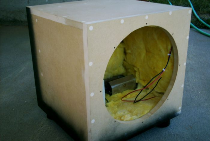
Figure 12. The assembled box.
I now needed an acceptable finish; but how to do it? Wood veneer was not cheaply or easily obtained in my area at that time, unless...you buy finish-grade plywood. Bingo. A couple sheets of white-oak laminated 1/4"(6.5mm) stock were obtained, cut, and glued into place using construction adhesive. A load of bricks provided valuable assistance:
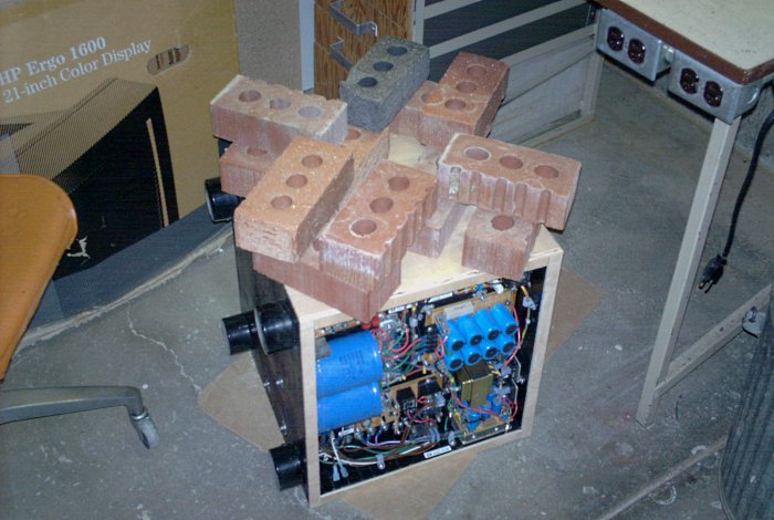
Figure 13. Oak-veneer plywood being installed.
Not only did the plywood provide an oak finish at reasonable cost, it had a second benefit: the lamination of the plywood to the MDF made the box noticeably more rigid.
The final step was to finish the cabinet somehow. Unfortunately, I didn't understand the multi-part process required for black laquer, and my first effort involved having the paint department at a local store attempt to add black tint to the darkest oil stain on the shelf. I tried it on the cabinet, was displeased, darkened it further, and tried again. The results were still not to my liking:
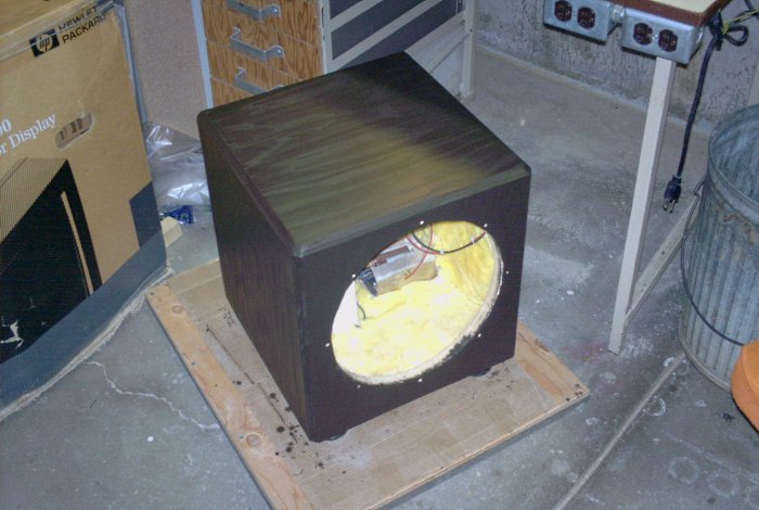
Figure 14. Two stain attempts yield darkening shades of mohagany.
This not being the 1970s, the burnt mohagany motif wasn't doing the trick, although ironically in the years since this build, dark cabinetry has returned to fashion under guilesome lingo such as "espresso." In frustration, I sanded the stain off the entire surface, and accidentally discovered a new effect. The stain had gone deep into the oak grain, which remained dark even as the surface came clean. Intrigued, I applied a light-oak tint. The results were now more to my liking:
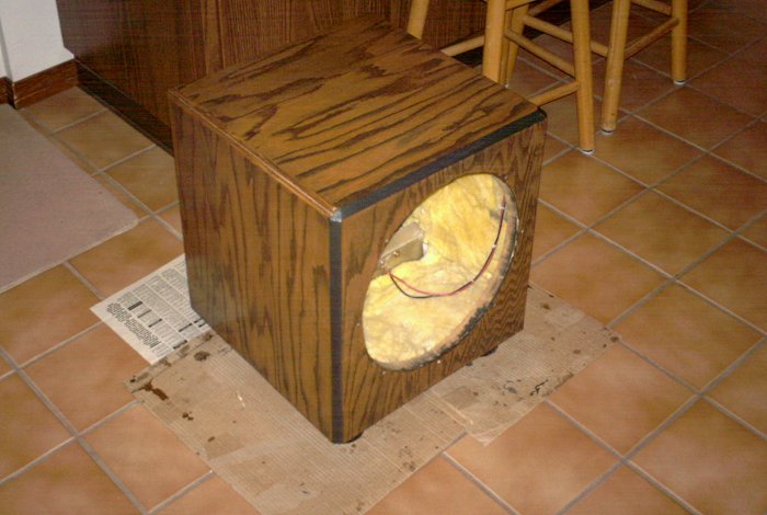
Figure 15. The subwoofer cabinet's completed finish.
This I could live with. The rough edge of the plywood around the front was filled in with putty and sanded flat, then completed with a specially textured black paint to form an accent. The whole works was then finished with seven coats of polyurethane, interspersed by sponge sanding. The result was a semi-gloss finish that is very smooth and extremely durable. I've also since learned that black laquer requires a basecoat and several applications of clearcoat. I could have gotten there with a cheap can of flat-black spray paint followed by the same polyurethane top-coating process, but this turned out more interesting.
As the wood finish was curing, I began assembling the rear plate.
aaronv dot net -at- gmail dot com