One very big boom in an unexpectedly small package.
The basic electronics and box were assembled first. I was able to purchase and build subsystems on a piece-wise basis as funds permitted, so it was practical to piece these together while saving up money for the amplifier-related components and the driver, each of which would require a single large expenditure. As a result, the following were assembled and tested well ahead of the rest:
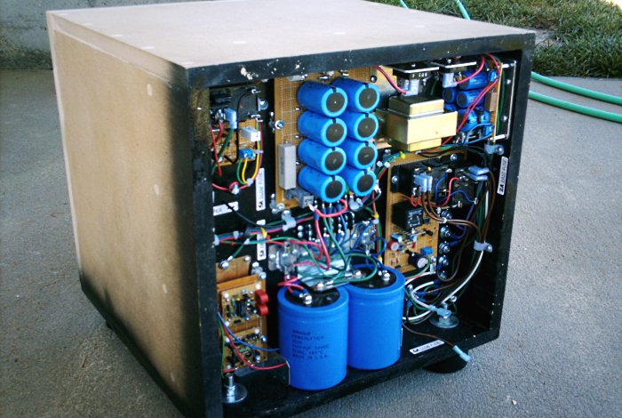
Figure 2. The back side of the subwoofer.
The diagram below highlights each major physical assembly:
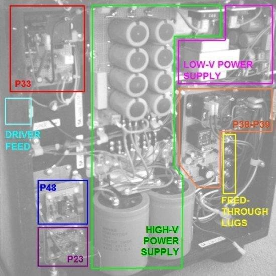
Figure 3. Major component assemblies identified.
The life-purpose of the P48 equalizer is described in the project article (see previous page). Summarily, a subwoofer is built into an undersized, sealed cabinet and the equalizer then severely overdrives it below the resonance point to create a flat response curve, at the expense of very high power requirements in the lower registers. Correspondingly, my cabinet was designed with a false back so the electronics could live somewhere ventilated while keeping the sub chamber airtight. The material is 3/4" (20mm) MDF, assembled in the usual carpenter's way of glue, screw, patch, and sand. The resonance chamber interior saw an application of silicone at the joint seams. Finally, the bottom side and the back were sealed with semi-gloss black spraypaint.
The P33 circuit is in the upper left corner and feeds through to the driver immediately below. The P48 equalizer and P23 clipping detector are placed at lower left, and the hybrid P38/P39 setup is located at center-right. Meanwhile, the low-voltage transformer and both bridge rectifiers are mounted on an aluminum plate at upper right, which also acts as a heatsink. Filters for the high-voltage section are situated down the middle, representing the exuberant waste of time and money produced when youthful enthusiasm meets novice inexperience. The amplifier would be more than happy with the twin 8800µF banks on top, let alone the dual 41000µF cans below. Live and learn.
Finally, for reasons of space, I had to install the high-voltage transformer and the soft-start ballast inside the main chamber. I decided to create pass-through connections by installing back-to-back T nuts through the MDF and terminating accordingly:
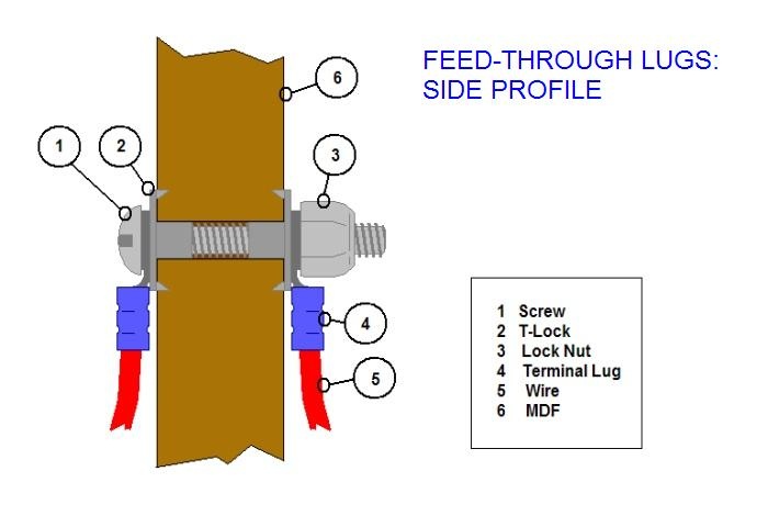
Figure 4. Custom screw terminals diagrammed in cutaway profile.
Each side of the connection can support multiple spade connectors if required. The screw heads and transformer connections are tightened down firmly inside the resonance chamber, as the rear connections needed to be unmade and re-made a couple times for testing. The resulting connection is airtight, mechanically stable, and makes an excellent electrical connection. Of course, the same thing could have been done by fishing wires through bare holes and backfilling with silicone, but since I needed some sort of terminal block for the AC section either way, this works.
Inside the chassis, we find the transformer and the other side of the feed-through lugs:
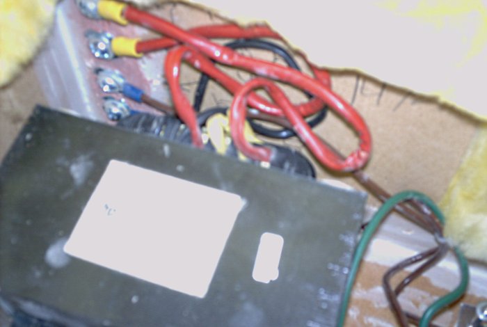
Figure 5. Transformer and pass-through connections.
As noted previously, the transformer is a 500VA EI/frame type unit, although it happens to be of excellent build quality and does not humm or buzz appreciably. The soft-start ballast lives next door:
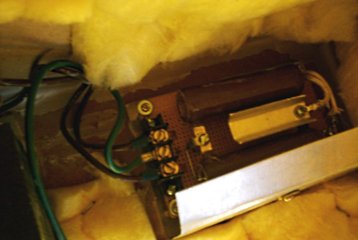
Figure 6. The soft-start ballast.
If that cap bank was a bit of a monstrosity, this is Frankenstein. The ballast is composed of two 40W, 80Ω power resistors in parallel and would serve well as a space heater. A single 10W, 20Ω unit would have sufficed for soft-start duty. Anyway, the center green wire is a ground wire for the ballast shield, which also daisy chains to the transformer frame. A failure condition at either device should create a ground fault and blow the master mains fuse.
Heavy things require heavy-duty mounting:
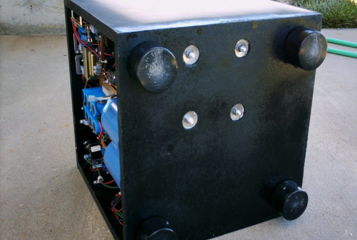
Figure 7. Bottom side of the sub box.
The transformer is firmly secured to the floor of the resonance chamber with carriage bolts. Countersunk holes with fender washers, completed with nylon-collared lock nuts, firmly secure the 18 pounds (8kg) of steel and copper. The resonance chamber floor actually has a two MDF layers at 1-1/2" (40mm) total thickness (rather than the single layer visible in back), so the countersink holes do not compromise the structure.
The feet were constructed from two ABS plastic pipe caps. The ends are somewhat rounded, which is fine for the outer foot, but the inner foot needs to be flush against the box. A few minutes with the bench grinder solved that problem. Two of the mounts are visible back in Figure 2. A side profile follows:
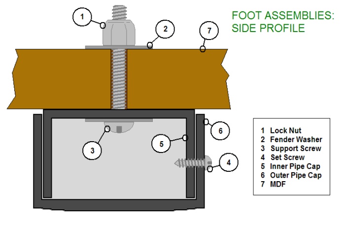
Figure 8. Custom foot assembly in side profile.
The foot design took a bit of careful thought, but the durable ABS plastic was a readily-available material that would look decent while handling the weight of the unit. I ended up using this method again on later speaker projects. A lesson that every DIY builder learns eventually, is this: plumbing supplies solve lots of problems beyond plumbing.
With all that out of the way, it was time to move forward on the amplifier.
aaronv dot net -at- gmail dot com