A low-profile affair with bridge-tied load.
Page 1 | Page 2 | Page 3 | Page 4
The power supply is based around two transformers. A 25VA EI-type transformer supplies an output of 25VCT for the low voltage control section, while a 400VA 18V+18V toroidal drives the main power supply. With this kind of power supply, the goal of 60Wx2 was not only realizeable, but the unit should be capable of sustaining close to full-power output, indefinitely, with both channels driven. For this build I ended up floor-mounting the 35A bridge rectifier, and although they are not visible in the picture, a pair of transformer protection fuses are mounted nearby:
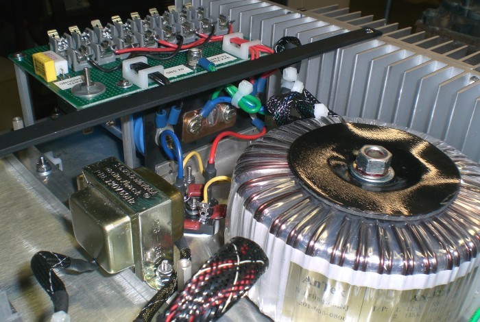
Figure 5. The power supply: Transformers.
The supply capacitors were a trickier issue. Not only were they a very hefty pair of 54000µF/35V can units I had scared up sometime previous, and therefore somewhat large, I also wanted to provide discrete twin fuses for each amplifier board. After toying with some ideas, I decided to mount the capacitor terminals onto a sort of L-bracket, then drop them sideways into the chassis. This would leave just enough room for the fuse holders to be plate mounted above the capacitors, and installed with tall standoffs. A section of L-bracket aluminum at the back of the array (facing the front of the chassis) supports a pair of rubber pads that press firmly against the can bodies, preventing the units from moving. It was one of the more unusual design ideas I've had to conjure but it seemed to do the trick:
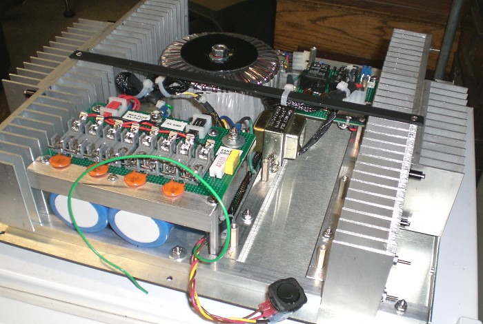
Figure 6. The power supply: Filters and fuses.
Visible on the inside edge of the fuse board is a ground loop isolator. A bidirectionally shorted bridge
rectifier (mounted below) shunts fault currents through its heavy-duty diodes, while a 10Ω power
resistor keeps the system 0V isolated from the chassis under normal conditions. A 100nF capacitor shunts
high frequency noise around the whole affair. For more details, see
this ESP article.
The main transformer and filters are plenty large, so a soft-start was in order. The ESP
Project 39 hasn't failed me yet,
and so it appears here once again. All amplifiers require service eventually, so as part of my ongoing
effort to make my projects more modular, the AC interface section is supplied with nylon Molex connectors:
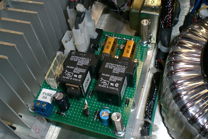
Figure 7. The soft-start board.
Additional standoffs are provided above the board because I anticipated placing the output muting and
protection module above the soft-start area.
The other half of the control section is the DC supply and control relays. Linear regulators were used to ensure a stable DC supply that is unaffected by voltage fluctuations, for example if the fan circuit is ever tripped.
Two relays respectively control a system high-temperature fan and a shutdown circuit. Both 65C and 85C self-resetting thermal switches are attached to the heatsinks at the rear of the enclosure and a trip on either heatsink switches the appropriate relay. The fan engages for a 65C trip to ventilate the chassis, and an 85C trip cuts power to the soft-start circuit and shuts down both amplifier sections. Ideally, neither condition ever occurs, and in practice the heatsink only gets lightly warm under idle in a typical room-temperature ambient, but the function is present for the safety of the unit.
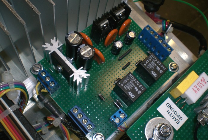
Figure 8. The DC control section.
The final part of the control system is the output muting and protection relays. These are driven by an ESP Project 33 circuit board. The actual ESP circuit has been modified slightly to accommodate four input channels, which are situated on the lower board section with the AC shunting capacitors clearly visible. As built, the circuit keeps the speaker outputs disconnected and shunted to ground for about two seconds after initial power-on, then mutes them again for a power-off cycle or a fault condition.
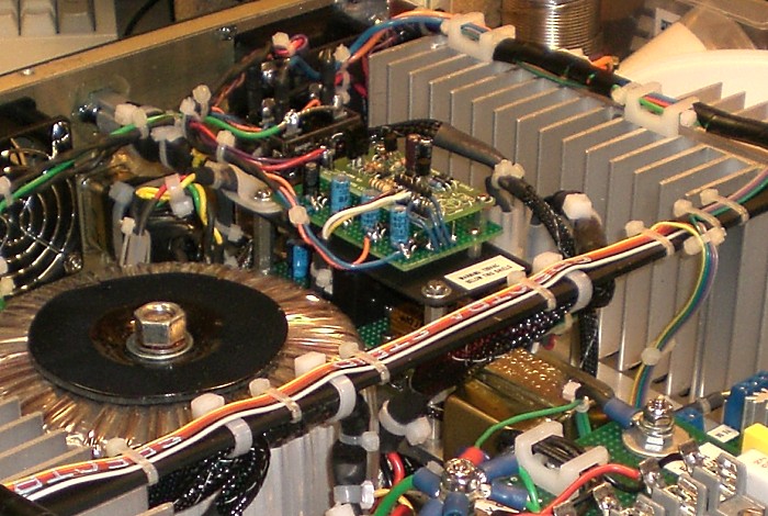
Figure 9. The output muting and protection circuit.
The location for the thermal switches isn't ideal, but space constraints forced them to the back end of the heatsink arrays. In any case, they're far better than nothing:
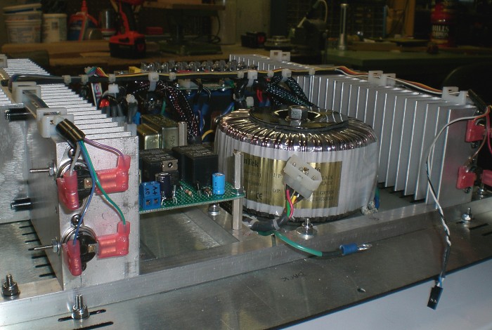
Figure 10. Thermal switches control the fan and overheat shutdown modes.
Also visible in the above picture is the main AC Molex connector, intended to interface to the inlet on the
rear panel while allowing the rear panel to be cleanly detached from the system.
With the main chassis largely assembled, it was time to complete and install the rear panel.
Optimized for a 1024 viewing width ~//~ All content (c)2008 aaronv.net