A low-profile affair with bridge-tied load.
Page 1 | Page 2 | Page 3 | Page 4
This idea was born from the confluence of two events: My roommate was engaged to be married in less than six months, and ESP forum contributor Liam had gotten the itch for another HEXFET amplifier design, this time a low-voltage setup in bridge-tied load for about 60-75W channel. This, in turn, had produced some spare boards. He offered me four at a reasonable price, and I saw in them a project idea that could solve my need to find a wedding present, since both my roommate and his fiance had expressed admiration for my previous projects.
I wanted to follow the same build philosophy as my Project 101 amplifier, but using a low-profile chassis. The amplifier would only output slightly under half as much power, so the smaller form factor seemed reasonable.
A "bridge-tied load" simply means that instead of driving the load between amplifier and 0V, the load is driven between two amplifiers. One amplifier drives in-phase and the other runs antiphase (180 degrees opposed). The result is twice as much voltage applied to the load for any given level of input as compared to driving the load with a single amplifier operating against 0V. A noteable consequence is that the effective input sensitivity is increased by 6dB, which may aggravate any existing noise and hum problems. Another effect is that each amplifier sees twice as much current as compared to driving the load alone, or effectively half of the load impedance if you prefer. If the driver is rated at 8Ω nominal, each amplifier behaves approximately as though it were driving a 4Ω load.
The boards had been ordered from a low-volume custom fabricator capable of doing double-sided etching with through-hole plating. There are no silkscreen markings, but as Liam had supplied me with the original design artwork, the boards were simple enough to construct:
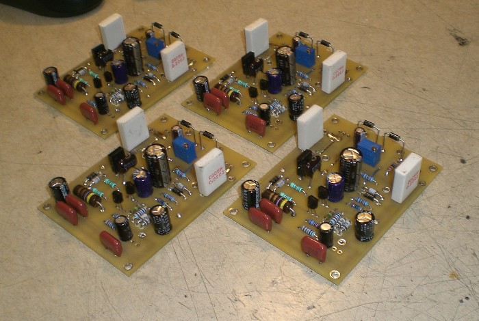
Figure 1. The newly-constructed boards sans output devices.
Each amplifier is intended to house an IRF640/9640 pair. While not technically complimentary, these
devices can produce acceptable results with a nice hot quiescent flowing across the output stage. They are
also extremely rugged, and since the plan was to drive each amplifier with just 20V rails, they also ought to
be nearly immune to brief short-circuits. As MOSFET devices they can be crudely protected using a Zener
clamping circuit on the gate, and in this application they are being operated way below their maximum design
power.
The 3W resistor packs were, interestingly enough, pulled from a small lot of failed stereo receivers I had
partially scrapped out after determining that some of the units were beyond repair. I had to modify the
boards slightly to fit them, but the clean layout made for a small and easy rework job.
With the amplifiers selected, it was time to build a suitable heatsinking array for each pair. By "suitable", of course, I mean very large. I never had reason to regret overbuilding the sink arrays on my P101, and since this unit would be out of my possession and probably subjected to a bit of accidental abuse, bigger is better. A suitable result was achieved by bonding three sink sections together in a T-configuration, which were test-fit to ensure that all was well:
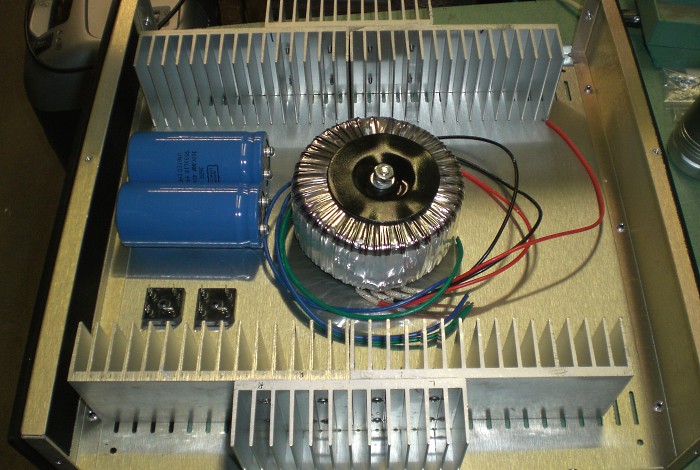
Figure 2. The heatsinks and a rought estimate of final layout.
All six sinks were originally identical, but to allow room for amplifier mounting, the center sink on each side had to be cut down a bit (notice the 13 fins instead of 16). Each sink trio was mounted together with eight stainless steel screws and nylon-collared lock nuts, with silicone thermal compound filling in the interfaces. They were mounted onto their own sub-assemebly, and PCB standoffs and #4-40 stainless steel screws were added as amplifier mounting hardware:
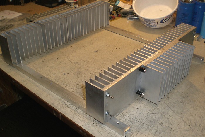
Figure 3. The heatsink assemblies.
The aluminum U-channel sections serve two purposes. First, they elevate the sinks off the chassis floor for improved convection air flow, and second, they improving the chassis rigidity. An overhead steel cross-brace was added afterward for imrpoved vertical stability, and the transformer mounting bolt was installed:
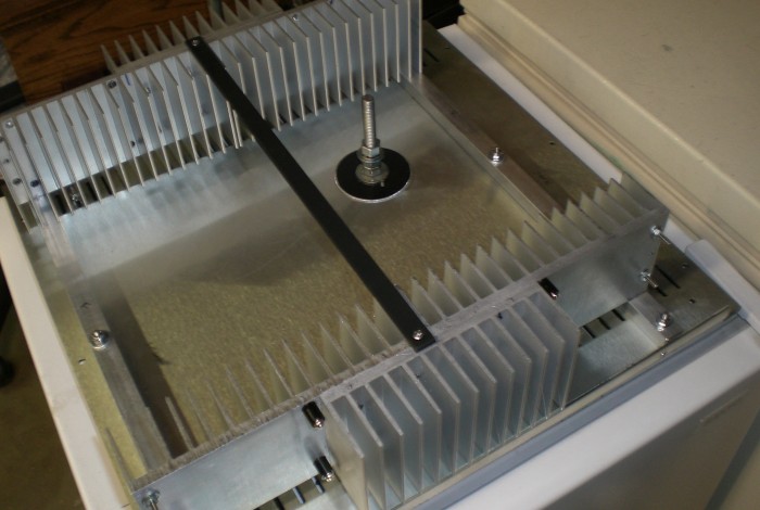
Figure 4. The final installed sinks and transformer bolt.
Since the front panel would only house a centrally-mounted power switch, and the rear panel area must have
space to handle the system power and audio I/O hardware, the sink assemblies were mounted fully forward in the
chassis.
With that done, it was time to work out a practical power supply configuration.
Optimized for a 1024 viewing width ~//~ All content (c)2008 aaronv.net