An experiment with HEXFETs.
Page 1 | Page 2 | Page 3 | Page 4
To securely connect the two boards, I decided to strip the jacket from a few lenghts of #14 solid-core AC mains wiring and use that to link all of the high-current sections. The low-current connections were achieved with standard wiring, like so:
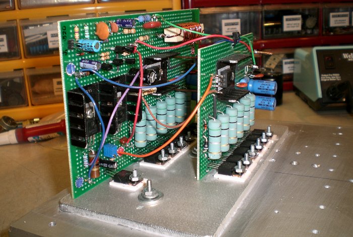
Figure 8. The linked boards.
When mounting thirteen devices to one heatsink, there are lots of opportunities to botch things. After one failed attempt to mount directly to the sink, I scrapped that idea and instead went with the old standby of 1/4 inch (6.5mm) aluminum. The #4-40 mounting screws are countersunk from the back side of the plate, allowing the transistors to be mounted with nuts. The plate then mounts flat to the heatsink:
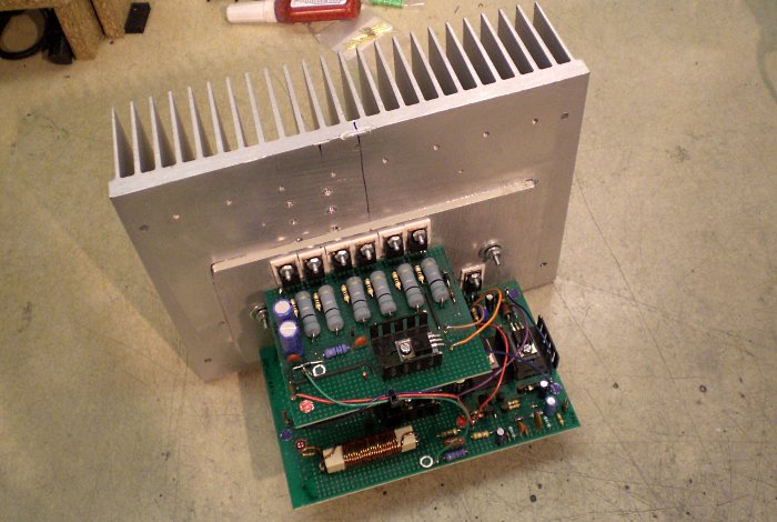
Figure 9. The fully assembled amplifier.
The decoupling capacitors have been changed in these photographs, because the originals were rated for
63V and the final DC rails hover somewhere in the range of 65-70V. A pair of 47µF/100V units per
rail will suffice in place of the original 220µF part. At that point the amplifier was successfully
tested at low voltage. it was time for the serious tests:
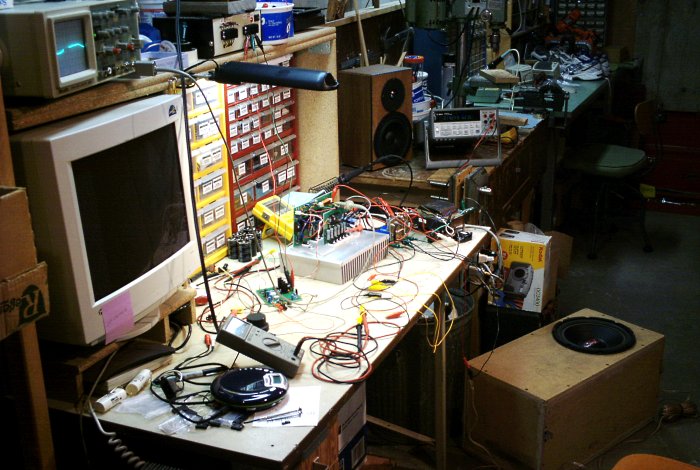
Figure 10. The amplifier undergoing high-voltage tests.
Nobody here but us windows, rattling in time with the beat. I don't like working with a rat's nest of
clip lead wiring as done here, since there are lots of ways to get things crossed and blow stuff up, but
in this case, it wasn't feasible to build the power supply first. The amplifier underwent several days'
worth of testing, saw a couple component values change as a result, and was finally deemed ready for the
big time.
The final verdict was a whopping 325W of power into an 8Ω resistive dummy load at the onset of
clipping, which was pretty impressive considering the 300VA transformer. Granted, it wouldn't do that
forever without burning out said transformer, but even so: Not bad!
I won't belabor these next circuits, as they are fairly straightfoward implementations of ESP projects that have made an apperance before. First, we have an ESP Project 23 clipping indicator, which operates by comparing the current output to the supply rail of equal polarity:

Figure 11. The Project 23 clipping detector circuit.
There is an ESP Project 33 loudspeaker protection and muting circuit with a nice, hefty power relay to handle the high output current from the amplifier:
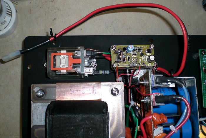
Figure 12. The Project 33 muting and protection circuit.
A modified ESP Project 43 equalizes the subwoofer inside an undersized chamber, in the same fashion as my previous P68 subwoofer. The LM79xx supply regulators are integrated with the circuit:
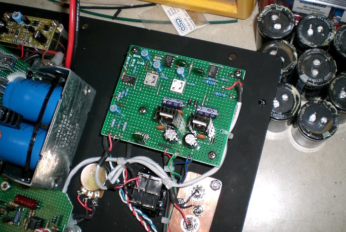
Figure 13. The Project 43 equalizer circuit.
And finally, an ESP Project 38 provides signal-detecting power-on function:

Figure 14. The Prject 38 signal-detecting power-on circuit.
This plate amplifier is functionally identical to my P68 amplifier, but this time, it was constructed with
somewhat better sense of how much is needed versus how much is too much, and I was also able to fit all components
on one plate.
The plate itself required a fair bit of layout and cutting, which we will review next.
Optimized for a 1024 viewing width ~//~ All content (c)2008 aaronv.net