Version 2.0: Featuring improved appearance and bug fixes.
Upon finishing my first attempt at the Elliott Sound Products Project 70 Class-A headphone amplifier, I derived two conclusions. The first was that a headphone amplifier is a very nice thing to have. The second was that a version 2.0 model was in order, one which would resolve the naiive design problems I had memorialized in the first. An external heatsink would be mandatory. Fan cooling was unacceptable. And the output should be absolutely silent at idle.
By this time I was discovering the wealth of non-RadioShack resources availble both locally and online, so the need to obtain a heatsink, a chassis, and proper transistors was no longer a hindrance. A suitable quantity of BD139 and TIP3055 parts (the recommended project transistors at the time) were obtained, the boards were ordered from ESP, and I was ready to go. This time, there would also be construction pictures.
Amplifier board assembly was undertaken first, as the boards and their mounting location would dicate layout for everything else. Coffee, my omnipresent dietary staple, is also pictured:
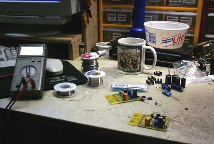
Figure 1. Birth of the Version 2.0 DoZ-HP amplifier.
The amplifier boards were finally completed and a small heatsinking 'flag' was added to the BD139 predriver pairs.
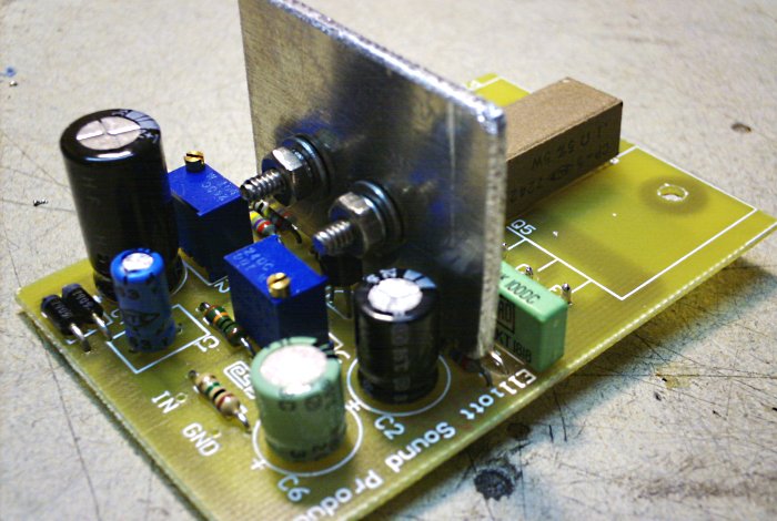
Figure 2. A completed board using the Elliott Sound Products PCB.
With that completed, I had to determine how to best mount everything in the chassis. After some deliberation and fidgety component measuring, I determined a workable layout, crossed my fingers, and began making holes.
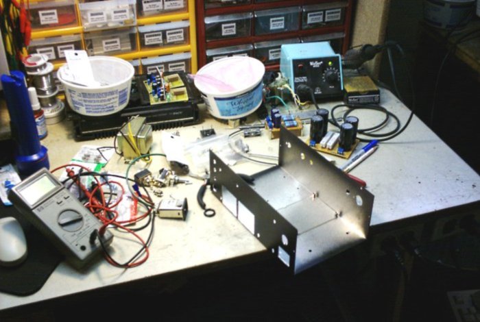
Figure 3. Preparing the chassis for final mounting.
This time an aluminum cabinet had been found, and unlike the steel case used in the V1.0 build, it was easily machined. A total of five mounting holes for the heatsink allow it to provide reinforcement to the rear of the chassis, which now featured several gaping scars.
Visible in the middle of the chassis floor is a polycarbonate mounting pad to insulate the bottom side of the filter bank, since the only low-profile PCB standoffs I had availalable at the time were a bit too low for comfort. Sure, nobody ought to be pushing them down in there, but novice paranoia is as novice paranoia does.
The amp went together quickly once the metalwork was done, yielding the completed layout as follows:
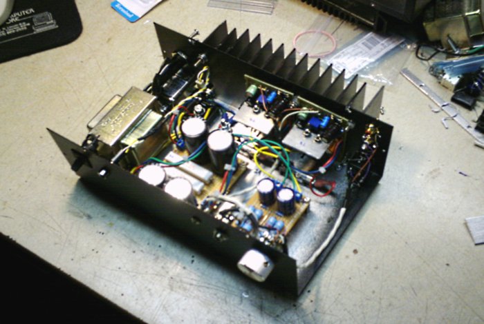
Figure 4. The completed layout from an overhead view.
Power entry occurs through an IEC inlet and a master fuse, and the Active (hot) lead passes through the front power switch on the way to the transformer. The transformer output feeds through a chassis-mount bridge rectifier on its way to the main filters.
The two amplifiers are mounted against the heatsink, which is mounted externally and vertically to guarantee optimal convection airflow. Power is sourced to each board through separate DC rail fuses on the positive single-supply lines. The DC output blocking capacitors and source-loading resistors are on a seperate PCB at the front-right corner, below the headphone jacks. Both 1/8" (3.5mm) and 1/4" (6mm) jacks are provided, with separate loading resistors for each.
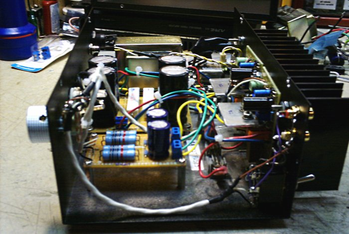
Figure 5. The completed layout from a right-side view.
Line inputs include RCA jacks and a 1/8" (3.5mm) jack. The toggle switch flips the channels, a useful feature if the 1/8" input jack is being used with a source that outputs reversed channels.
At this point, the amplifier was nominally done...but there was hum and buzz! That was unexpected. After some discussion on the ESP forum and follow-up experiments, the culprit was the non-isolated input jacks. These, on account of having an electrical connection to the chassis, were creating a four-way ground loop back to the grounded 0V point of the power supply. Well, now I knew better. The jacks were isolated using nylon washers and a bit of jury-rigging, and the amp was fine thereafter.
aaronv dot net -at- gmail dot com