In which I construct my first serious DIY audio project.
When I first discovered DIY audio, I was hunting big game, specifically a subwoofer. I knew I could never afford to buy a commercial powered subwoofer at that time, but DIY offered the possibility of getting the performance I wanted at maybe one-third the cost. I was underemployed at the time, which left me with excess time but a shortage of money, and I knew that my dad, by whose good graces I was not yet homeless, would be more understanding of this interest if I built useful skills. Electronics and woodworking would both qualify.
I also had a newly-minted electrical engineering degree to my name, but analog electronics theory, transistors in particular, never quite stuck. In general I do not grasp the theory of anything unless I have a practical illustration to analyze. A few audio projects, I reasoned, might be a way to start turning that 'C'-average college transcript into an 'A'-level knowledge set. I already had a passable soldering technique, but before diving into big things, I first needed proof that I could build something smaller.
After browsing the projects list at Elliott Sound Products, I had my answer: Project 70, the DoZ Class A Headphone Amplifier. It was something I could use effectively, since I'm an incurable night owl. And it didn't require any complementary transistor pairs, so I knew I could build it with locally-procured RadioShack parts. (My discovery of other local shops with better parts selections didn't come until later.)
The value of a headphone amplifier is often underappreciated. Any output transducer, however large or small, requires appropriate current in order to be driven effectively, especially in the bass range. Nothing can help a bad driver with poor response, but even a good driver will sound tinny and weak if it is starved. And until the revolution in mobile devices occurred after about 2010 or so and forced the major audio IC and DAC manufacturers to up their game, it was uncommon for an average headphone output to be truly good. I didn't understand the practical reasons for this at the time, but I had played around with enough headphone jacks and unpowered speaker systems to know that something was at work. At any rate, a headphone amplifier would be an interesting thing to have.
After a good scrounging through spare parts, followed and a shopping excursion, the bill of materials included the following:
I was cutting the output devices a bit close, since the TO-220 package offers limited surface area against the rigors of Class A dissipation, but at the time I didn't fully understand just what kind of cooling this thing would need. Then there were my limited heatsinking options, which amounted to aluminum bits pulled from failed computer power supplies. And I knew I would need a fan to properly ventilate what was, at the time, my only option for a halfway decent cabinet-style chassis.Transformer: 50VA 120VAC 60Hz primary, 24.2V CT secondary Large filter caps (scavenged from an old instrumentation power supply) Bridge rectifier Small steel cabinet chassis MJE3055 output transistors (Q3, Q5) TIP31 predrivers (Q2, Q4) 2N3906 input transistor (Q1) Miscellaneous resistors, capacitors, audio I/O hardware, etc.
So...what resulted? Unfortunately, I didn't acquire my first digital camera until a couple months after this project was completed, so there are no construction photos. The completed unit looks like this:
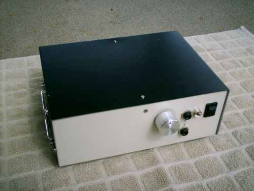
Figure 1. Front view of the DoZ HP amplifier.
The unit has a passive volume control pot (100k log) between the rear inputs and the amplifier, two 1/4" (5mm) headphone jacks in parallel, a power indicator LED, and an AC power switch. The grill on the unit's left side is where the exhaust fan is located.
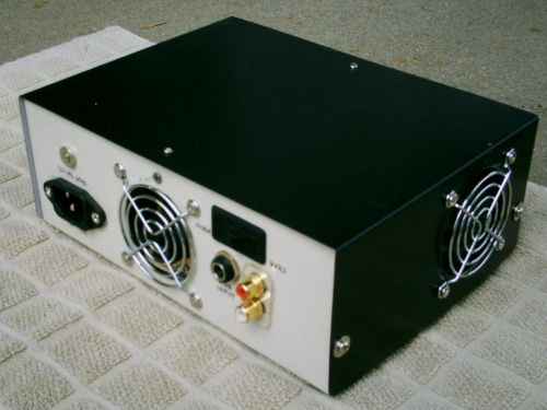
Figure 2. Rear view of the DoZ HP amplifier.
The back side features an IEC inlet, an intake vent, and a choice of either a 1/4" (5mm) or RCA line inlet jacks, wired in parallel. A slider switch flips the channels, a useful function if the 1/4" input jack has been connected to a source that has the channels reversed.
Now we get to the interior. An overhead shot reveals the basic layout:
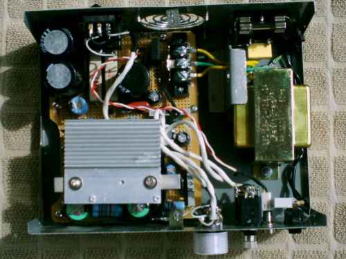
Figure 3. Overhead view of the amplifier's layout.
On the far right, the IEC inlet feeds the hot (active) lead through a fuse before hitting the front panel switch, then services the transformer. The transformer output feeds the circuit board via a terminal strip, encountering a bridge rectifier and filters. Pretty standard stuff, really. I had been building low-voltage supplies for small projects long before this, so all this was typical. Less typical was the resistor-dropped, split-supply layout to the amplifier channels. From here forward, I was doing my best to follow the ESP schematics. The amplifier portion was where this got tricky, since the cooling issues had to be considered.
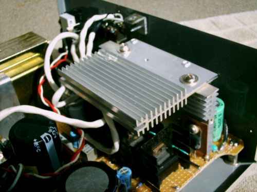
Figure 4. The amplifier heatsinks.
The black TO-220 style heatsinks in a neat row are the TIP31 predrivers. An output device is visible on the vertical heatsink. The overhead section was bolted onto the assembly when initial experiments revealed I had greatly underestimated Class-A's ability to pour out the heat, even at the reduced power levels this design requires. The output resistor and blocking capacitor for each channel sit in front of the main heatsink, next to the chassis front wall.
The fan is mounted to the chassis topcover. It lands in front of the heatsink assembly, hence the notch in the circuit board. The arrangement creates a turbulent wind tunnel and is stable in spite of the odds against it. The heatsink temperature (and by extention, the amplifier's quiescent current) stabilizes within a few minutes and has survived several hours' use in ambient temperatures as high as 90F (35C) without thermal runaway.
Results were mixed but I remained encouraged. Sure, there was fan noise, an uncomfortable amount of heat exiting the vent, and electrical hum in both channels. I figure unresolved grounding issues and generally poor layout on the board are both to blame for the latter. But it worked! And that was enough. I knew I could move forward on my other plans. I also resolved that I would eventually build another version of this amplifier, using an improved layout, a large external heatsink, and the ESP circuit boards with better output devices.
Meanwhile, I started construction on my subwoofer, and built a small power amplifier to continue improving my skills. That amplifier actually became the second of my early projects. Various bits of the subwoofer were already taking shape, but the unit would not be completed for about a year.
The DIy audio bug had bit me, hard. From these beginnings came my most enduring and focused hobby. Check out other articles on the site to learn how that hobby took shape and expanded. §
aaronv dot net -at- gmail dot com