300W and beyond with forced-air cooling.
In power measurement there are two specialty transformers that permit a system to be measured indirectly. One is the voltage (potential) transformer, known in shorthand as a VT (PT). It converts one voltage to another at a fixed ratio in the usual way, but with guaranteed precision and limited power output.
The other is the current transformer (CT). A clamp ammeter is type of CT, where current in a single primary wire induces a secondary current in the clamp, which the meter can measure without tapping directly into a primary circuit that may be rather dangerous. For permanent installation, a common CT form looks like any toroid transformer, but does not have separate HV and LV windings around the core. Instead, a current-carrying primary wire is passed through the middle and a secondary winding on the core develops a secondary current output that is proportionate to the primary. Up to its design limit, the CT will push this current into a short-circuit loop all day long.
In consequence, a relatively small load resistance placed in series with the CT will quickly be driven to relatively high voltages. I had a notion I could wind a miniature CT and use its output to indicate current flow through the dummy load by measuring the voltage created across such a resistor.
I was wrong, and we'll explore that in a minute. The idea was simple enough: Just spin a few enamel wire turns onto a ferrite core, use a variac and a dummy load (how ironic) to pass a current of known magnitude through the center, and measure the CT output across a small resistive load. If the voltage developed across the resistor followed a predictable curve, then a sequence of comparator circuits could be used to light LEDs indicating the approximate loading in a fashion similar to a bar-display dB meter.
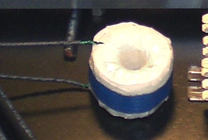
Figure 5. The home-brew current transformer.
I went to a lot of effort to make it look pretty, but looks alone can't atone for a lack of personality. That being said, the bench-test results seemed viable:
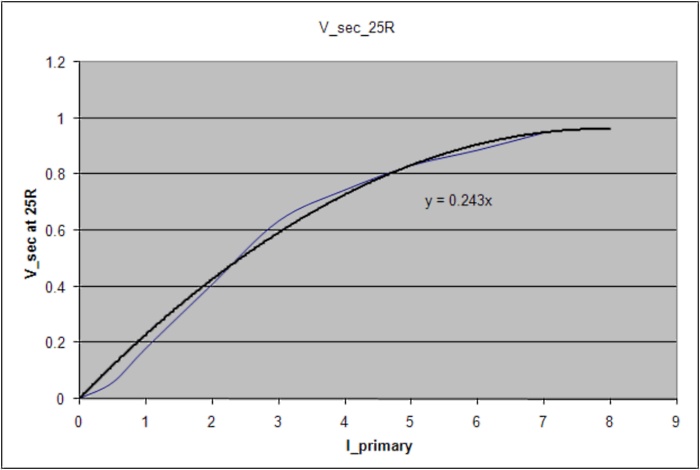
Figure 6. The CT output with a curve-fit.
What this chart was telling me (I thought) was that I had a reasonably clean relationship between current input and a generated seconary load voltage to at least 500W (8A primary into an 8R load). If I could create four opamp comparator circuits and then adjust them with trimpots to trigger sequentially, a row of LEDs could be used to indicate the approximate power dissipation in the dummy load. And that is what I went about building, along with a power supply for both this circuit and the low-voltage fans:
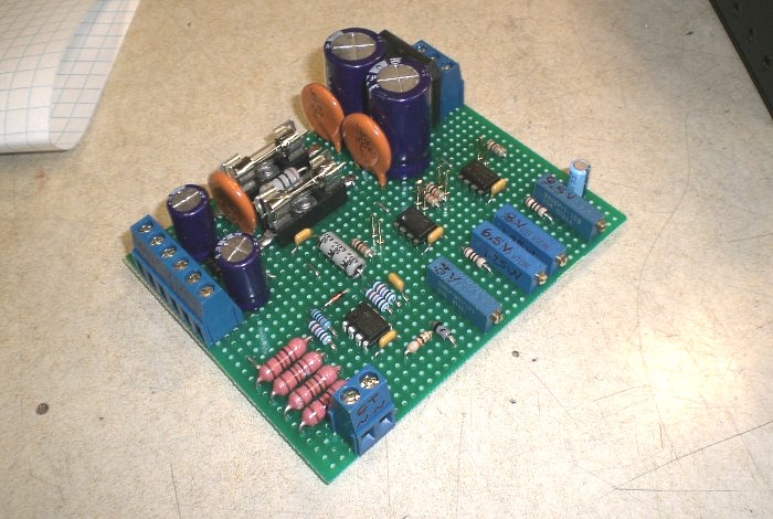
Figure 7. Power supply and sequential comparator circuit.
The concept was sound: the CT pushes through a small load bank, the first dual opamp buffers and boosts the voltage signal measured across the bank, and the second two opamps are dual comparators reading that boosted signal against a reference voltage.
Two points: first, if you're going to build a precision circuit, give it a precision power supply. The circuit tested nicely on the bench when reference DC signals were applied. It then fell into a whimpering mess as soon as the load of five ball-bearing fans and a power relay were applied to the same supply, causing noticeable voltage droop. An LM317/337 voltage regulator pair would have been very useful here.
Second, if you're going to wind a CT without any regard for design calculations, at least do it on proper transformer core steel. Ferrite is fine for high-frequency applications but the seemingly-neat performance curve I generated on the test bench was nowhere to be found after final assembly. To this day, none of the power indicator LEDs will operate. I later procured an actual commercial CT that might have done the trick, but by then had moved on to other projects.
Regardless, these discoveries were still in the future, and i went about test-fitting the kit ahead of final assembly:

Figure 8. Test-fitting the components in the chassis.
From here, it was time to start cutting holes in the chassis and screwing things up (so to speak).
aaronv dot net -at- gmail dot com