300W and beyond with forced-air cooling.
My first dummy load was a simple affair of two 40W, 4Ω banks with simple, but functional, construction. It was also cheap. Nothing wrong with that, but I had already built a couple amplifiers capable of 300W or more, and also had a couple future ideas in the 800W+ range. Ceramic power resistors have a decent instantaneous power handling well above their free-air continuous rating, but one has to draw the line somewhere. I have not grenaded a power resistor (yet) but I've read testimonials from a couple people who have. They don't recommend it.
I had previously used a pair of 30W, 80&Omega ceramic tube resistors in a massively overbuilt soft-start for my P68 subwoofer, and knew where I could buy sevearl more. In short order, an idea was born. Possibly not a good idea, and definitely not a sane idea, but this is DIY. Sanity is optional.
High-power resistors can sustain a lot of heat. Well and good for the resistor, but mounting can be something of a pickle. Fortunately, I needed all the resistors in parallel for both electrical and cooling purposes. That meant it was time to make friends with threaded rod and related hardware:
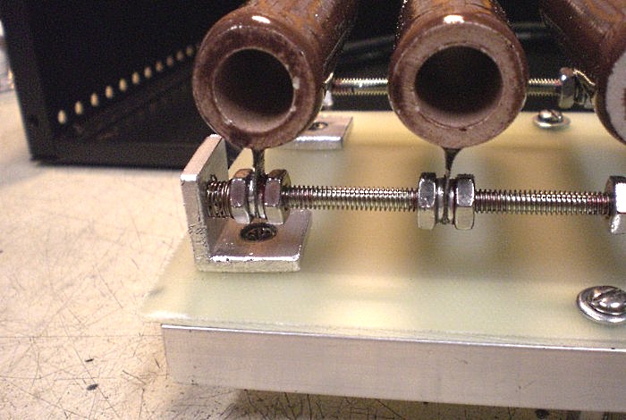
Figure 1. The ballast assembly takes shape.
The rod serves as both a mechanical support and an electrical connection. Insulation from the chassis is achieved by attaching the assembly to a fiberglass plate, which is then rigidly attached to aluminum U-channel and elevated with stand-off mounts. Two of those L-brackets for mounting the rod also serve as the electrical interface on the bottom side. The cable is copper AWG #8, type THHN, and should have no trouble withstanding residual heating through the terminals:
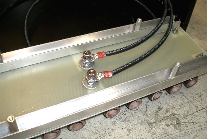
Figure 2. The terminals access the load from the bottom side.
To take the load's continuous power rating beyond the 300W free-air, forced-air cooling is needed. Five fans and a low-profile chassis, with low-restriction wire guards, make for a nice wind tunnel:
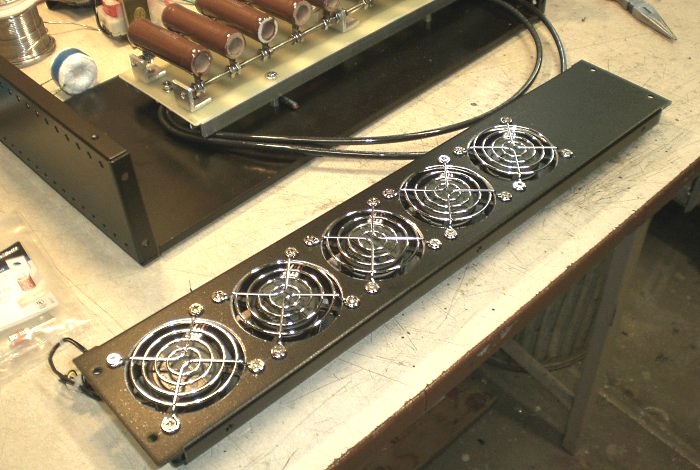
Figure 3. The fans, installed in the back panel.
All fans are exit-facing, which puts the chassis under negative pressure. Another view from the inside:

Figure 4. The ballast mounts against the fan array.
The arrangment should be good for maybe 1000W sustained load, because Why Not. At the very least, the chassis is rigid steel with a thick aluminum faceplate, and should contain the shrapnel if this thing is ever driven too far.
Next task: Figure out a way to measure the power through the ballast.
aaronv dot net -at- gmail dot com