Just like a professional unit, but for less than $50.
Readers who have already browsed my "Early Projects" section will recall two attempts at building a Class A headphone amplifier, the second of which was very successful. Unfortunately, the power supply and heatsinking requirements for Class A place constraints on the minimum feasible size, and I was in the mood for something more in a slimline format.
I had been examining Elliott Sound Products' Project 113 for some time, and when I found a stack of $10 slimline-chasses in the surplus store, I knew instantly how I was going to build it. Just to be thorough, I was going to place a buffer between the line inputs and the volume control pot, based on a single-stage conversion of ESP's Project 88. Finally, an external plugpack power supply would use internal LM7x12-series regulators to provide a suitable symmetrical supply with minimal space requirements.
Project 113 is a very slick little circuit. It starts out as an ordinary opamp driver, but to avoid loading the opamp, the device serves only as an input stage and voltage amplifier while the heavy lifting is handled by a discrete output stage. The additional current avoids the undesirable effects of opamp overloading, especially with unusual headphone impedances. The original design is based around BD139 and BD140 TO-126 devices, but I was building from scratch and had MJE15032/33 pairs on hand, so why not go for broke?
The only catch was that the slimline chassis I had found does not seperate in the middle -- it is basically an extruded rectangular tube with end panels and interior circuit board rails. No matter, my dad had scared up some large scrap protoboard from a discard bin at work, and it was only a minor engineering challenge to make everything fit:
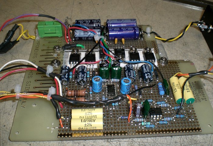
Figure 1. Birth of the Slimline Headphone Amplifier.
On the back of the board, an AC 18V input crosses to a fuse and power switch at the front, then crosses back again through a simple voltage doubler and capacitor network to LM7812 and LM7912 DC regulators. The output of those passes through another capacitor bank (notice how the use of radial-style units allows for high quantities of filtering in a shallow chassis) and feeds the amplifier and preamp buffer. The P113 amplifier sits in the middle and the preamp buffer lies front and right.
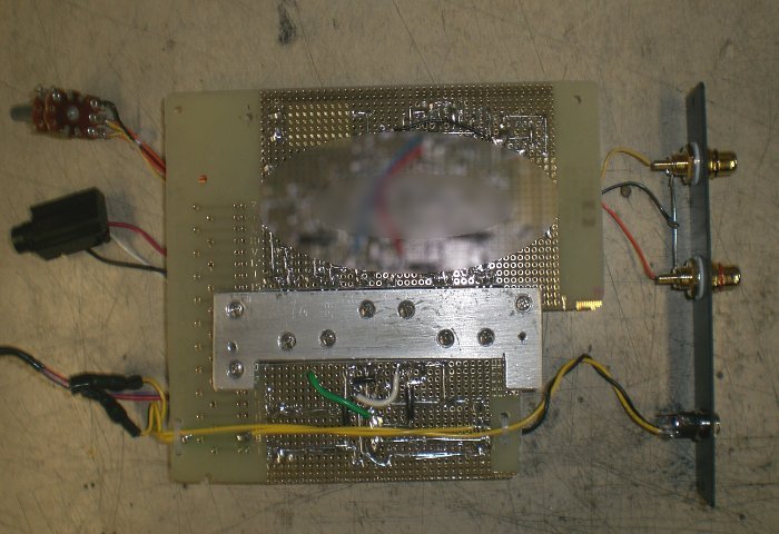
Figure 2. The bottom side, showing the heatsink block.
The regulators could technically run without heatsinking, but the amplfier channels require at least a little.
And when building inside an unvented chassis, sinking to the chassis is usually the best thing. In this case,
a small section of 1/4" (6.5mm) aluminum plate did the trick. The six TO-220 devices (two regulators, two
amplifier channels) mount to the plate using screws countersunk from the back side, and the plate then mounts
to the chassis. (The PCB trace area is nothing special, but out of deference to ESP's intellectual property,
it has been obscured in Figure 2.)
Other hardware visible in the previous image includes the isolated input jacks, the coaxial power supply jack,
the 1/4" (6.5mm) headphone output jack, the stereo volume pot, the leads and disconnects for the power switch,
and the leads that feed a white LED power indicator.
The board was inserted into the chassis, and the front panel was assembled as a final step. The end result had exactly the look I wanted:
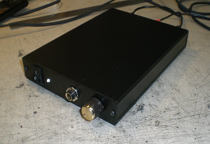
Figure 3. The completed unit as viewed from the front.
In keeping with a minimalist form, the white LED has no bezel; it simply presses tightly into a drilled hole. Also, I only included a 1/4" (6.5mm) headphone jack this time, leaving 1/8" (3.5mm) operation to the graces of a jack adapter. The back side shows even less:
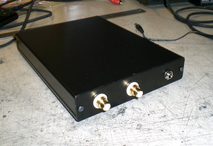
Figure 4. The completed unit as viewed from the back.
Nothing here but us input jacks -- line left and right, and 18VAC.
How does it work? Extremely well, I'm pleased to say. I ended up tweaking the gain a couple times before getting a result I was completely satisfied with, but nothing else is objectionable here. It adds enormous value to any pair of headphones and manages to look good while doing it, and the plugpack supply greatly simplifies the grounding and shielding issues that can occur, since the chassis can be tied to 0V with no earth ground whatsoever.
There's no reason why this unit couldn't be made half as deep, but this was good enough for me, and the size and price on the chassis were close enough to ideal that I have no complaints. It looks small, it performs big, and unlike my previous Class A headphone work, this runs extremely cool. No complaints.
Optimized for a 1024 viewing width ~//~ All content (c)2008 aaronv.net