The from-scratch, 1970s-style chassis concept, revisited.
The first integrated amplifier in my "Newer Projects" section was a mostly from-scratch build of a stereo amplifier in a 1970's-style chassis with a wood cover. I had an itch to do it again, but this time building exclusively a two-channel amplifier (i.e., no preamp hardware) and wanted to avoid some of the irregularities in my first build which, fortunately, did not affect the sound or the appearance from the front.
My first attempt at this project involved a HEXFET design using dual IRF640 devices per channel. Without going into the details, suffice to say it was an experimental design which I never got to work correctly, and I abandoned it, leaving the chassis, power supply, and ESP Project 39 soft-start (self-powered version) power supply on the backburner for, uhm, several years. But I finally got the inspiration to finish it, including ordering up another board for the ESP Project 33 muting and protection circuit, which I consider indispensable for any amplifier project.

Figure 1. The HEXFET amplifier design, since abandoned.
That left the question of what amplifier to use in place of the abandoned design. Now, regular readers of the ESP Project Pages may recall that when Rod Elliot sells a high-power version of the ESP Project 68, he supplies the expansion board for the additional output devices by cutting the front-end off a second project PCB. However, there is nothing wrong with these front-end cuts other than the fact that they are missing the output stage and a future. At some point, Rod had shipped me a couple of these as a sort of thank-you gift along with another large order, suggesting I might figure out some novel application for them, given my past history in building and modifying his designs.
Regular readers of the ESP sight may have also noticed that since most ESP designs have a single designer, useful design elements tend to be replicated across multiple project layouts. One of the most vivid is the Project 68 subwoofer amplifier, and the ESP Project 3A power amplifier; the front-end layouts are nearly identical, except that P68 includes an input ground lift and a simplified voltage amplifier stage. Having worked with P3A before, it occurred to me that with minor modifications, the P68 offcuts could be modified into P3A amplifiers. Conveniently, I could retain the P68's input ground lift. (It tends to increase the noise threshold slightly, but makes a dramatic decrease in ground loop problems.) The trickiest part was making space for the variable resistor that adjust the bias.
Since I was intending to build the resulting amplifier around the +/-25V power supply I had already assembled, I knew I could derate the design just a bit, particularly the output resistors, and the result (along with the P33) was a trio of very neat-looking boards.

Figure 2. The finished P68-to-P3A conversions, and P33.
The previously-assembled power supply and soft-start circuit utilized a pair of very hefty 35,000uF, 35V snap-in type capacitors I had previously purchased from a surplus shop. The remainder of the linear supply, including the self-powered P39 soft-start and DC secondary fuses, all fit nicely onto a single power supply board.
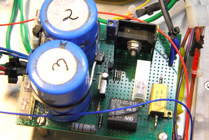
Figure 3. The power supply board, including soft-start.
The bridge rectifier could be used without heatsinking, but this was DIY, and small aluminum heatsinks are cheap at
surplus. So are aluminum-bodied ballast resistors.
The chassis was built completely from scratch, which meant I had to come up with my own ventilation holes beneath the sink. I achieved the layout shown in Figure 4 by using a drill press and a stepper-bit to achieve the hole sizes I needed, then mill the hole slightly on both sides. The side braces could have been aluminum or phenolic, but in this case I found some pieces of heavy polycarbonate plastic in the scrap collection. Conveniently, I was able to embed four acorn nuts into mounting holes, allowing the chassis top to mount with four base screws almost identical to the classic assembly method for many 1970s receiver and amplifier chassis designs.
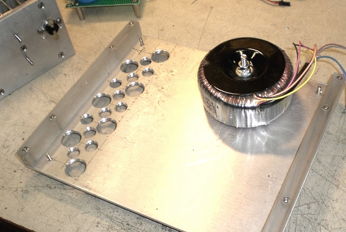
Figure 4. Development of the chassis base.
The side panels were constructed, then connected together with a top piece and vent, made from pre-drilled aluminum and given a sanding treatment and clear coat to achieve final appearance. An early test fit of chassis pieces, which were made from red oak, proved the design would work out quite well:
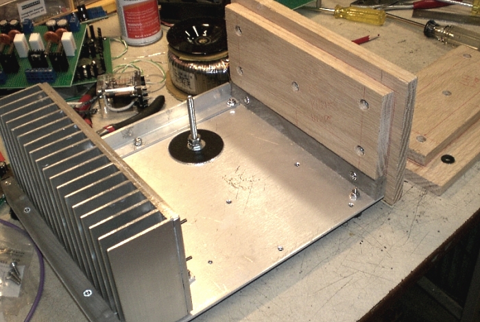
Figure 5. Checking the fit of the side panels.
The remainig electrical was a straighforward matter of wiring and layout checks. A view of the final PCB installation shows the amplifiers mounted just beyond the DC supply points and P33 off to the side. The thermal switch, visible in an earlier image, cuts power to the P33 relay if the heatsink temperature exceeds 65C. So far, it has never operated.

Figure 6. Final PCB installation.
Since both amplifiers share a common heatsink, the bias needed to be tuned in parallel to ensure that both tracked roughly the same as the heatsink temperature rose and stablized. A pair of multimeters made fairly simple work of it.
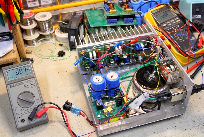
Figure 7. Setting and verifying the bias for good quiescent current.
The final result? Good all around:
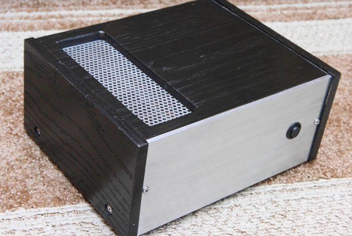
Figure 8. Front view of the finished unit.

Figure 9. Rear view of the finished unit.
The amplifier works as well as any P3A, and any loss in noise floor from the ground lift is negated by the
device's preferred application, which is a pair of bookshelf speakers and the typical reduced efficiency
that can be expected from such units.
As always, the basic design underlying P3A proves to be highly flexible and stable for low-to-medium voltage
applications (here, about 25-30W/channel), and both the novice and moderately experienced builder can do well
by adding another one to their collection.
Optimized for a 1024 viewing width ~//~ All content (c)2008-2015 aaronv.net