Test nearly anything at 24V and less.
The solder was still cooling on my first serious audio projects and it was clear some sort of benchtop power supply was needed. Now, there are good commerical supplies available, usually with adjustable voltages to at least 24V, and current-limited outputs. They also cost way more money than I could spare at the time, not with what I had planned for my upcoming subwoofer project.
What I did have was a well-built 10-0-10 transformer lying aorund in a junk box, a hefty bridge rectifier, and a smattering of other miscellaneous parts including terminal strips, panel-mount LEDs, and small switches. Mix thoroughly, bake in a medium oven for about three hours, and out comes a usable power supply.
The supply design was developed as follows (click for larger):

Figure 1. Generalized schamatic diagram for the PSU. (Click image for a larger view).
This doesn't show the full layout of the IC voltage regulators, but that is easily developed from any data sheet or a quality project design such as Elliott Sound Products' Project 05. The main DC voltage from a rectified 10V transformer winding would not reliably drive a 12V IC regulator, so the 12V circuit is a shunt regulator loosely derived from a power supply idea in Elliott Sound Products' Project 37, using an MJE3055 for the regulator transistor as it was cheap and readily available.
The transformer output is rectified and filtered to DC rails slightly above 12V, which are fused and then made available for general purpose testing of symmetrical devices and anything needing a 24V supply. The positive rail is tapped over to regulators with switchable outputs, allowing for regulated test voltages at 12V, 5V, and 3.3V. These cover most common single-supply applications, including logic, low-voltage opamp circuits, relays, fans, and so forth. Finally, indicator LEDs show what is on and what is not.
A few hours later, and the result was a credible bench power supply:
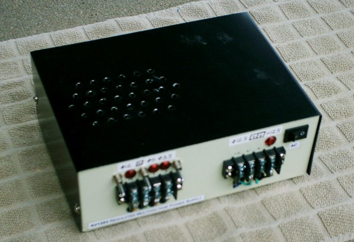
Figure 2. Front view of the bench power supply.
This image was taken with an old camera, so the details are fuzzy. Summarily: the left-hand side offers a four-position terminal block, three switches, and three indicator LEDs. The outputs are +12V, 0V, +5V, and +3.3V.
On the right-hand side lies another four-position block, this time featuring the unregulated outputs of +12.5V, 0V, 0V, and -12.5V. The master power switch is on the far right-hand side. As indicated in the earlier control schematic, the master power switch enables the unregulated outputs and delivers power to the regulator bank; each regulator output is then switched independently.
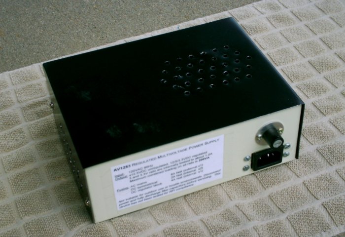
Figure 3. Rear view of the bench power supply.
The rear side simply contains the IEC power inlet for supplying AC to the transformer, and the master fuse.
The interior is cramped, but everything fit. A rear overhead view reveals the layout:
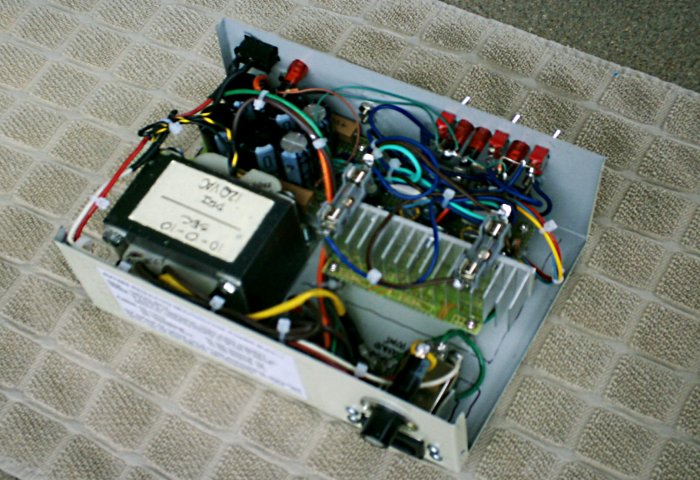
Figure 4. Internal view of the supply layout.
At the rear left corner (facing the viewer in this angle) are a filtered IEC inlet and mains fuse holder. Power then routes around to the transformer primary, with the Active lead passing through the master power switch at the front corner. Secondary enters a chassis-mount rectifier between the transformer and IEC inlet, and the rectifier output feeds a filter bank near the AC power switch. The output of that is guarded by the two DC fuse holders on top of the regulator heatsink, which are routed out to the unregulated outputs and the regulator section.
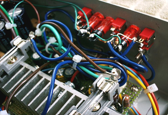
Figure 5. Close-up view of the regulator area.
The heatsink supports the TO-220 type regulator IC, and the supporing circuitry lives on the perfboard section below.
One flaw exists in this design: the DC rail fuses are inside the chassis. It is regrettably easy to kill a 2A fuse with even a minor slip of a test lead, which here means disconnecting the AC and removing the lid. These really should have been installed in front-panel holders with thumb-screw tops.
Otherwise, it does the job, and has seen many hours of use. It is eventually destined for replacement by a heavier-duty unit with current-limiting circuitry, panel-mount fuses and circuit breakers, and an additional high-voltage section for testing amplifiers at full operating power. Until then, this will continue to serve and I have no plans to modify the fusing, mostly because the as-built layout is too cramped.
There is another variation to this concept that is adjustable and doesn't require specialty parts: LM3x7-style adjustable regulators wired to a common control pot. Elliott Sound Products' Project 44 is a practical implementation, and if voltage display is desired, panel meters are easily incorporated. Some LM3x7 regulators are limited to as little as 800mA per rail, but even this is more than enough for most basic equipment tests. As always, when working with IC voltage regulators, pay careful attention to the different pinouts. The negative-rail devices tend to fail short-circuit if wired in the fashion of a positive-rail device.
Need a power supply of your own? There is not much to this unit other than time and a handful of common parts. §
aaronv dot net -at- gmail dot com