Safety in a big, heavy package.
Having analyzed the control section, let's move on to assembly.
An old carpenters' adage recites as "measure twice, cut once." This applies equally to machinists, including weekend hobbyists pretending to be machinists. In my case, I always start by laying out the equipment on my workbench at a very early stage in the project. Not all sub-assemblies are necessarily built, but a rough arrangement of the largest bits (e.g. transformers, heatsinks, and large filter capacitors) provides a fair estimate of how much house you need to buy. When in doubt, order the next larger size. Extra chassis space is cheap if you have it and priceless if you don't.
It is a good idea to do the same thing several times during the assembly procedure, before the drilling and filing gets out of hand. Like so:
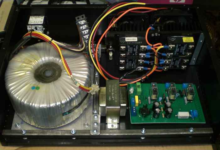
Figure 10. Testing the layout for good fit and suitable wiring clearances.
At this stage, it is important to ask questions such as, Is this a good fit? Will the wiring route well? Do I have clearance for front-panel hardware? The process is tedious, but few things will kill your mood so quickly as seeing a sleek, expensive chassis accidentally turn into Swiss cheese as one "oops" is corrected by another "oops" followed by a "what if I just..." followed by "oops again," and eventually concludes in a rage-quit.
In this particular test-fit, the chassis size had been established earlier and the transformer location and rear-panel layout were not negotiable, so the reinforcement and rear panel were already completed. The important thing was to ensure that the heatsink would fit in front of the fans and the control circuitry would fit in the remainder.
Next step: Actually installing things. The heatsink was first, since it must live in front of the fans. The main transformer was marked off for clearance and saved for last, for obvious reasons. The vertical stacked layout I created in front of the heatsink was not the original plan, but while testing the fitment, the following idea occurred:
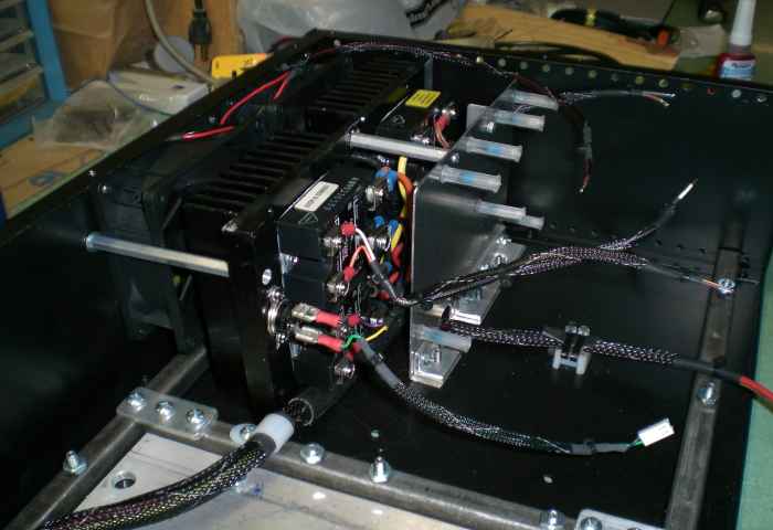
Figure 11. Installing the sink and control board.
Not only does this approach make good use of space, it places a grounded shield immediately in front of the high-voltage area -- one more safety precaution in the event a wire should ever work loose. The nylon standoffs were used because they were available. I usually prefer metal hardware but these had been salvaged cheaply from defective stereo receviers which, at the time, I was procuring in cheap lots on eBay for a mix of repair/resale and parts scrounging. Wiring, meanwhile, is protected with braided nylon sleeving. Wire ties and wire clamps prevent cable from flopping around. These are mostly an aesthetic touch but it never hurts to provide extra wiring protection within equipment that could see field use.
Once the control board was installed and the wiring was tied down, it was time to mount the main transformer and finish wiring the high-voltage section:
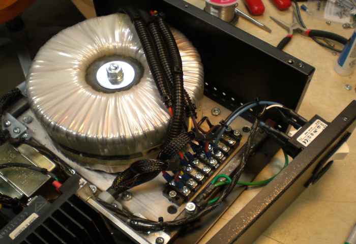
Figure 12. Main transformer installed and wired.
A terminal block is a great asset, provided it has suitable voltage and current ratings and is mounted securely in a place where curious fingers will not find it. Both incoming conductors arrive from the IEC-style inlet, feed immediately through the two-pole breaker, and then tie to the terminal board. The Active conductor hops over to SSR#1 and SSR#2, and the return line feeds the transformer. The transformer output also ties to the terminal board before heading over to SSR#3 and SSR#4 (see the system control diagram on Page 2 of this article).
To reduce corrosion risk, the terminals were dressed with an anti-oxidizing compound. It is dielectric grease impregnated with sacrifical zinc, and normally sold for use in older houses with aluminum wiring. But it works just as well for this application.
The isolated supply was nearing completion. All that remained was to construct and assemble the front panel:
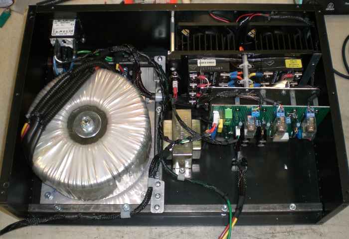
Figure 13. The supply is approaching completion.
Although there looks to be a lot of unused space in front of the control board, most of it is needed to fit the wiring for the front panel:
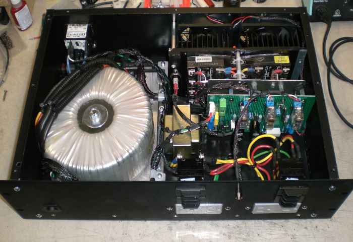
Figure 14. Front panel assembled and installed.
And there it is. Although not visible in this camera angle, a section of rectangular U-channel runs along the bottom of the front panel in order to prevent flexing.
aaronv dot net -at- gmail dot com