A basic 1970s BJT topology, built for practical experience.
Shortly after constructing my headphone amplifier, I commenced work on my new hobby's long-term goal: a powered subwoofer. Three new things soon came to my attention. First, more practical experience on a small project would be helpful. Second, it would be good to have a medium-voltage power supply available for testing my sub's amplifier section before kicking it on at full power. And third, the subwoofer construction would probably require the better part of a year, as I needed to finance a few hundred dollars' worth of parts on a limited income. This would leave me with time to burn in between construction stages.
The solution was to build a fairly simple Class AB amplifier, and make sure the power supply section was accessible for other uses. A small 48V center-tapped transformer had recently turned up in a junk box, and that was giving me ideas. (I didn't learn until much later that it was good for, at best, about 75VA.)
I had been reading through the projects list at Elliott Sound Products, and Project 03 seemed a good match. I was ready to order the transistors for my sub amplifier, so I added two pairs of TIP2955/TIP3055 to the bill, along with two of the BD139 part that serves as the voltage amplifier. Work commenced on the two input sections seperately from the output stages, and the former were partially completed when the transistors arrived by post.
Project 03, in the updated form shown in the article, is about as simple as a Class AB amplifier can reasonbly get. The long-tailed pair (LTP) at the input stage uses simple resistors to set the current instead of current-mirrors and the like. The voltage amplifier achieves a rudimentary current source via boostrapping. Both are cost-saving engineering tricks from the old days (i.e., when semiconductors could be several times more expensive and several times less reliable than passives). The output stage uses a complementary feedback pair (CFP), in which basic thermal stability is assured by the inherent feedback loop between the predrivers and output devices. The overall design methodology was pretty common in older amplifiers, and similar layouts can be found in many higher-end 1970s receiver designs. The CFP output can be prone to oscillation around the negative rail at high output, but so long as the rail voltage stays below 50V or so, it works fine.
Mind you, I didn't know most of this at the time. I just thought it was pretty cool that it all worked on the first try.
I bought my first digital camera about the time this unit was built, but had not yet realized that construction pictures might be a good thing to have. I simply tore through the P03 build from start to finish in a rush of inspired labor. Impressively enough there were no mistakes, and it worked fine on the first try.
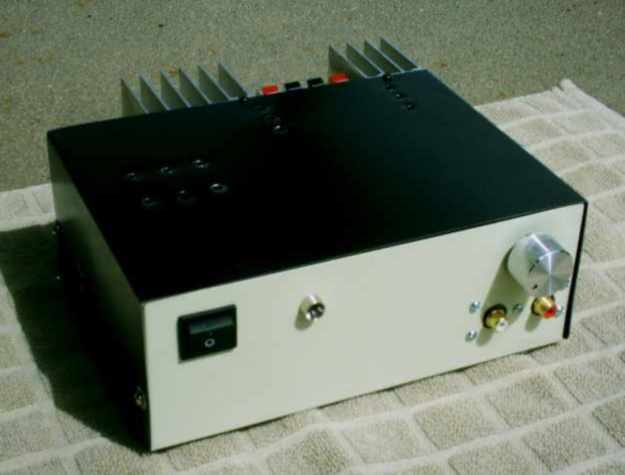
Figure 1. Front view of the 60W amplifier.
The chassis is small (and rather familiar-looking...be prepared to see it several times in my early projects), so the input jacks came to the front side of the unit. A passive volume control (100k log) sits between these and the amplifier, and the usual AC switch and power LED are also present.
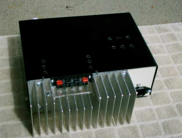
Figure 2. Rear view of the 60W amplifier.
On the back, there is an IEC inlet, speaker jacks, and a heatsink. The space requirements for the heatsink, relative to the size of the chassis, were responsible for the input jacks moving to the front.
An overhead shot reveals the basic layout of the interior:
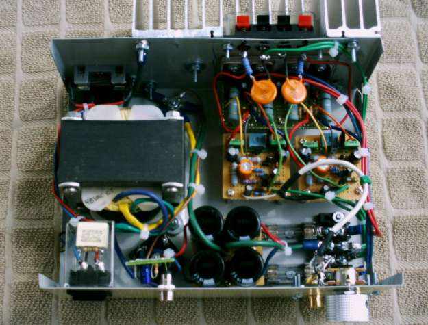
Figure 3. Overhead view of the amplifier's layout.
The power supply enters through the IEC inlet at upper left and the hot (active) lead immediately passes through a fuse before hitting the front panel switch and transformer. The components hanging from line to neutral on the double-pole AC switch are a poor-man's noise filter (0.1uF high-voltage polyester capacitor in parallel with a 1MΩ resistor). The transformer AC output feeds through a chassis-mount bridge rectifier into the filter bank, and then into a pair of DC rail fuses. After that, instead of traveling directly to the amplifier channels, it stops at a terminal block. The amplifier can be disconnected from that block and the supply is then available for testing external devices.
The amplifier, meanwhile, is split between three boards. Input stage and voltage amplifier occupy one board for each channel, and both output stages are roommates on the third board:
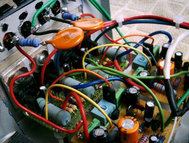
Figure 4. The amplifier circuitry up-close.
Other than the necessary evil of jumpering the the two front-end boards to the output stage, everything is clean and compact. The output Zobel network for each channel hangs from the speaker jack terminals in order to save board space. The BD139 voltage amplifiers are clearly visible next to the trimpots, with the bias servo transistor situated in front. Metal film resistors of wildly disparate power ratings litter the two front boards, simply because they were available in the spare parts drawers.
The amplifier works surprisingly well, considering it is crowded against its own AC power supply and has an under-rated transformer. Good enough for a test project, anyway, and the transformer doesn't heat up under test use.
The amplifier itself has a noticeable amount of hum, a problem which is unlikely to ever be cured. It served its purpose: I learned more about construction techniques, the detachable power supply was later used to test my subwoofer's amplfier section, and I used it several times afterward as a test device. After an hour or so the heatsink becomes distressingly hot, so I've never had a good reason to put this unit into regular service.
All things considered, the Project 03 amp was an excellent investment, even if it is outclassed by better designs and was constructed here in a crude fashion. The learning experiences that began with my DoZ headphone amp continued with this project, and paid off in spades when my subwoofer finally came together in one clean, working piece. §
aaronv dot net -at- gmail dot com